Rocket motor nozzle assemblies having vacuum plasma-sprayed refractory metal shell throat inserts, methods of making, and rocket motors including same

a technology of refractory metal shell and nozzle assembly, which is applied in the field of rocket motor nozzle assembly having a throat insert, can solve the problems of decomposition layer sheared off by high-speed gas stream, decomposition layer slipping, and nozzle throat receding, so as to reduce the exit area to throat area ratio (or expansion ratio) and eliminate the risk of nozzle failure

Inactive Publication Date: 2005-06-14
NORTHROP GRUMMAN SYST CORP
View PDF15 Cites 7 Cited by
  • Summary
  • Abstract
  • Description
  • Claims
  • Application Information

AI Technical Summary

Benefits of technology

[0017]In this embodiment, the carbon- or silica-based protective eyelid covers a sufficient portion of the forward surface region of the shell and the underlying converging portion of the throat support to protect these components against particle impingement and erosion. The carbon- or silica-based protective eyelid extends sufficiently far forward along the converging / diverging pathway to cover and protect the forward face or edge of the throat insert and prevent the combustion gases from passing under the throat insert and reaching the radially outer surface of the throat insert. Protection of this radially outer surface of the throat insert from combustion gases is necessary to eliminate the risk of nozzle failure that might otherwise occur if combustion gases were to reach underneath the throat insert. However, in accordance with the principles of this invention, the protective eyelid does not cover the throat surface region of the shell, thereby leaving the throat surface region of the shell exposed to the converging / diverging pathway. Since the refractory metal shell is much less susceptible to erosion than the carbon- or silica-based material forming the eyelid, the throat are a, which is defined by the refractory shell, is less likely to recede and thereby diminish the exit area to throat area ratio (or expansion ratio) of the nozzle.

Problems solved by technology

It is widely acknowledged in the industry, however, that carbon- and silica-based nozzle throats tend to recede, especially at high operating temperatures and pressures.
For example, in the case of silica-cloth phenolics and the like, material loss is attributed to thermal decomposition and melting of the liner material, which can cause the decomposed layer to be sheared off by the high-velocity gas stream.
In the case of carbon cloth phenolics and the like, material loss can result from the thermal decomposition of the liner material, which forms pyrolysis gas and char due to chemical reactions of the decomposed material (char) with the combustion gases.
The recession of the nozzle throat inner surface during motor operation is a source of several problems in rocket operation.
As the nozzle throat material recedes, the exit area to throat area ratio (or expansion ratio) diminishes, thereby decreasing the efficiency of the nozzle and causing loss in motor performance.
Another problem is having higher than predicted nozzle recession.
In-flight variations of nozzle throat diameter due to recession can reduce motor performance.
However, the weight penalty and expense associated with the presence of the tungsten and other refractory metals often make these refractory materials impractical and uneconomical for applications involving bulky throat insert cross-sections.
Additionally, refractory metals exposed to hot combustion exhaust gases and particles are subject to tensile stresses due to thermal shock early in motor burn when thermal expansions near the rapidly heated exposed surfaces are restrained by cooler regions of the cross-section farther from the exposed surfaces.
Such thermal stresses in both the axial and tangential (or hoop) directions can produce thermal fractures in the nozzle component, and potential ejection of the throat insert from the motor.

Method used


Image

  • Rocket motor nozzle assemblies having vacuum plasma-sprayed refractory metal shell throat inserts, methods of making, and rocket motors including same
  • Rocket motor nozzle assemblies having vacuum plasma-sprayed refractory metal shell throat inserts, methods of making, and rocket motors including same
  • Rocket motor nozzle assemblies having vacuum plasma-sprayed refractory metal shell throat inserts, methods of making, and rocket motors including same

Examples


Embodiment Construction

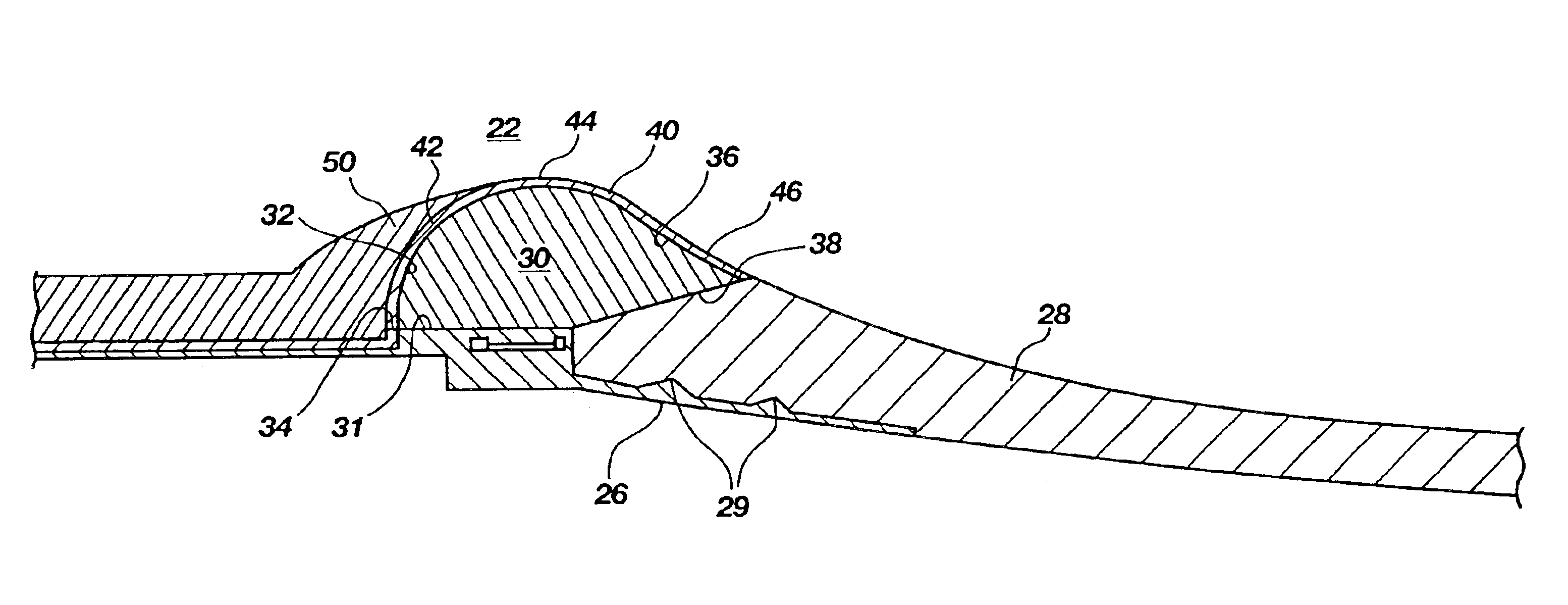
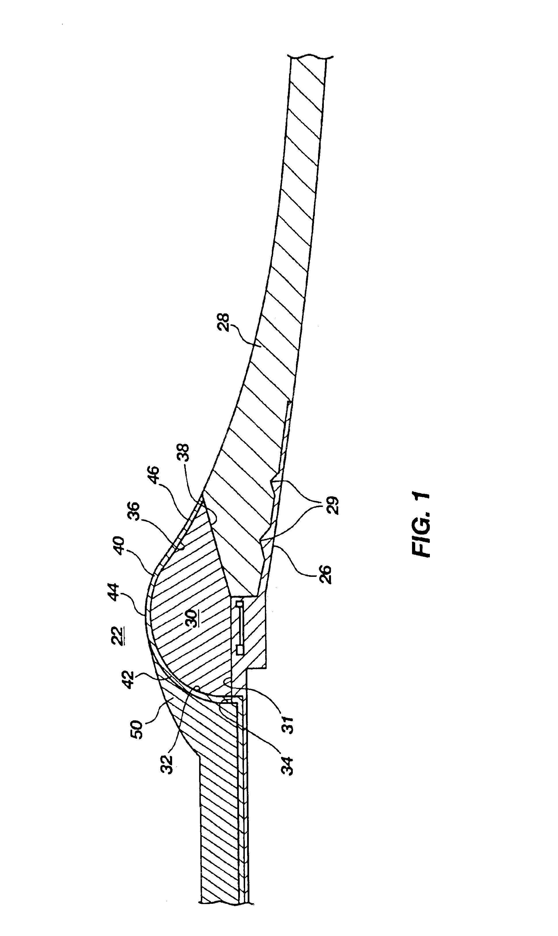
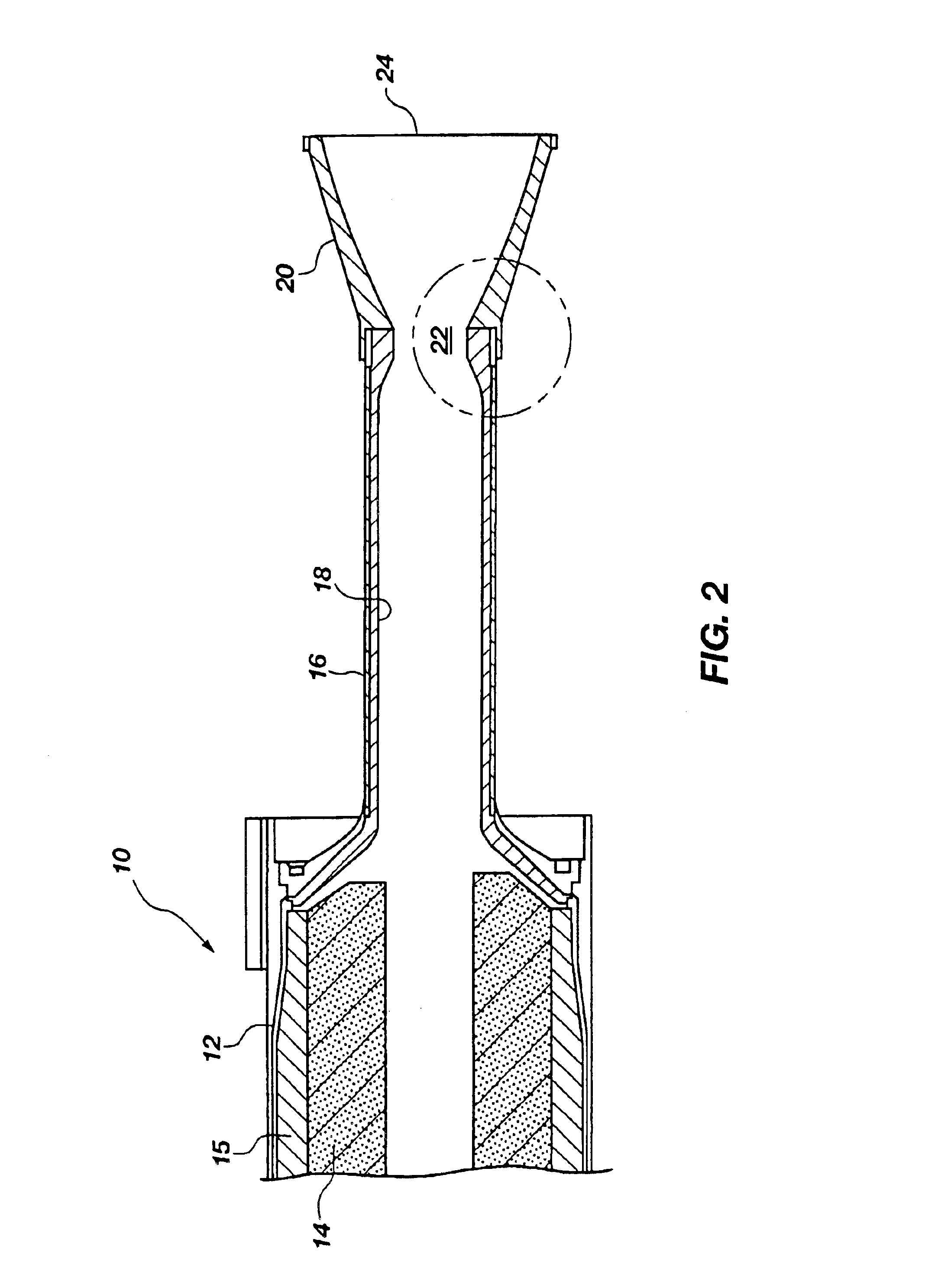
[0023]The general structure of a rocket motor engine is shown in FIG. 2, in which the engine is generally designated by reference numeral 10. The illustrated rocket motor engine 10 includes a case 12 in which a rocket motor propellant 14 is housed, a nozzle assembly 20, and a blast tube 16 connecting the case 12 to the nozzle assembly 20. In the illustrated embodiment, the rocket motor propellant 14 is in the form of a solid propellant grain. As shown in FIG. 2, the case 12 and the rocket motor propellant 14 commonly are separated by an insulation layer 15, as well as a liner (not shown). Similarly, the blast tube may also be lined with insulation, such as depicted in FIG. 2 and designated by reference numeral 18. The insulation layer 15 and the liner (not shown) serve to protect the case 12 from the extreme conditions produced by the rocket motor propellant 14 as the rocket motor propellant 14 undergoes combustion reactions and is exhausted through exit region 24 of the nozzle asse...


PUM

PropertyMeasurementUnit
melting temperatureaaaaaaaaaa
melting temperaturesaaaaaaaaaa

Abstract

The rocket motor nozzle assembly of this invention includes a throat insert and a carbon or silica protective eyelid. The throat insert has a carbon throat support and a refractory metal shell. The shell is positioned radially inside the throat support to cover the inner surface of the throat support. The protective eyelid covers a sufficient portion of the forward surface region of the shell and the underlying converging portion of the throat support to protect these components against particle impingement. The protective eyelid extends sufficiently far forward along the converging / diverging pathway to cover and protect the forward face or edge of the throat insert and prevent the combustion gases from passing under the throat insert and reaching the radially outer surfaces of the throat insert. However, the protective eyelid leaves the throat surface region of the shell exposed to the converging / diverging pathway.

Description

CROSS-REFERENCE TO RELATED APPLICATIONS[0001]This application is a continuation of application Ser. No. 09 / 765,781, filed Jan. 19, 2001, now U.S. Pat. No. 6,711,901, issued March 30, 2004, which is based on U.S. Provisional Application 60 / 177,218 filed in the U.S. Patent & Trademark Office on Jan. 21, 2000, the complete disclosure of which is incorporated herein by reference.BACKGROUND OF THE INVENTION[0002]1. Field of the Invention[0003]This invention relates to a rocket motor nozzle assembly having a throat insert that includes a vacuum plasma-sprayed refractory metallic component for preventing the throat from receding, and an ablative component constructed and arranged to reduce erosion under the refractory metallic component. This invention also relates to a rocket motor engine assembly comprising the nozzle, and to methods of making the rocket motor nozzle assembly and engine assembly.[0004]2. Description of the Related Art[0005]Conventionally, solid rocket motor propellants c...

Claims


Application Information

Patent Timeline
Patent Type & Authority Patents(United States)
IPC IPC(8): C23C30/00C23C4/00F02K9/97F02K9/00H04L5/02H04L27/26
CPCC23C4/00C23C30/00F02K9/974H04L5/023Y10T29/49346F05D2300/502F05D2300/13F05D2300/2263F05D2300/224
Inventor CANFIELD, ALAN R.SHIGLEY, JOHN K.
Owner NORTHROP GRUMMAN SYST CORP
Why Eureka
Try Eureka