Stabilized OLED device

a technology of electroluminescent devices and stabilized oleds, which is applied in the direction of discharge tube luminescnet screens, other domestic articles, natural mineral layered products, etc., can solve the problems of inability to meet the requirements of many practical applications, the oled device emits color contaminating light, and the luminance output is gradually degraded, so as to improve efficiency and stability, improve stability and performance, and reduce angular dependence

Inactive Publication Date: 2005-06-14
GLOBAL OLED TECH
View PDF4 Cites 54 Cited by
  • Summary
  • Abstract
  • Description
  • Claims
  • Application Information

AI Technical Summary

Benefits of technology

[0014]It is an advantage of the present invention that it provides a monocolor OLED device with improved stability and performance. It is a further advantage of the present invention that it permits the use in an OLED device of stabilizing materials that have emissions at unwanted wavelengths without such unwanted emissions affecting the desired emissions. It is a further advantage of the present invention that it provides a light source for a color-conversion type OLED display with improved efficiency and stability. It is a still further advantage of the present invention that it provides for the use of a full-color OLED display with improvements from the microcavity effect but with reduced angular dependence that commonly affects microcavities.
that it provides a monocolor OLED device with improved stability and performance. It is a further advantage of the present invention that it permits the use in an OLED device of stabilizing materials that have emissions at unwanted wavelengths without such unwanted emissions affecting the desired emissions. It is a further advantage of the present invention that it provides a light source for a color-conversion type OLED display with improved efficiency and stability. It is a still further advantage of the present invention that it provides for the use of a full-color OLED display with improvements from the microcavity effect but with reduced angular dependence that commonly affects microcavities.

Problems solved by technology

This gradual degradation of luminance output is unacceptable for many applications.
As a result, the emitted light from the OLED device is contaminated in color by the emission from the stabilizer.
This contamination may not be acceptable for many practical applications.
With this approach, full color displays have many advantages, however, one of the key problems is that blue emitting OLEDs are generally the least stable and least efficient of OLED devices.

Method used


Image

  • Stabilized OLED device
  • Stabilized OLED device
  • Stabilized OLED device

Examples


example 1

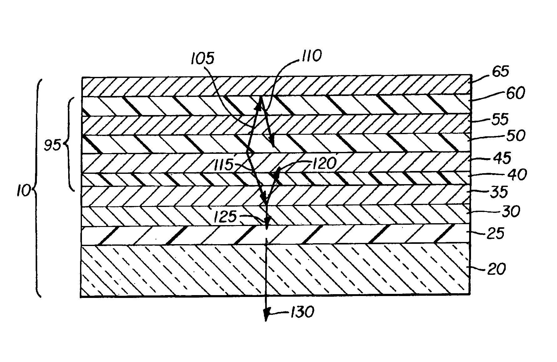
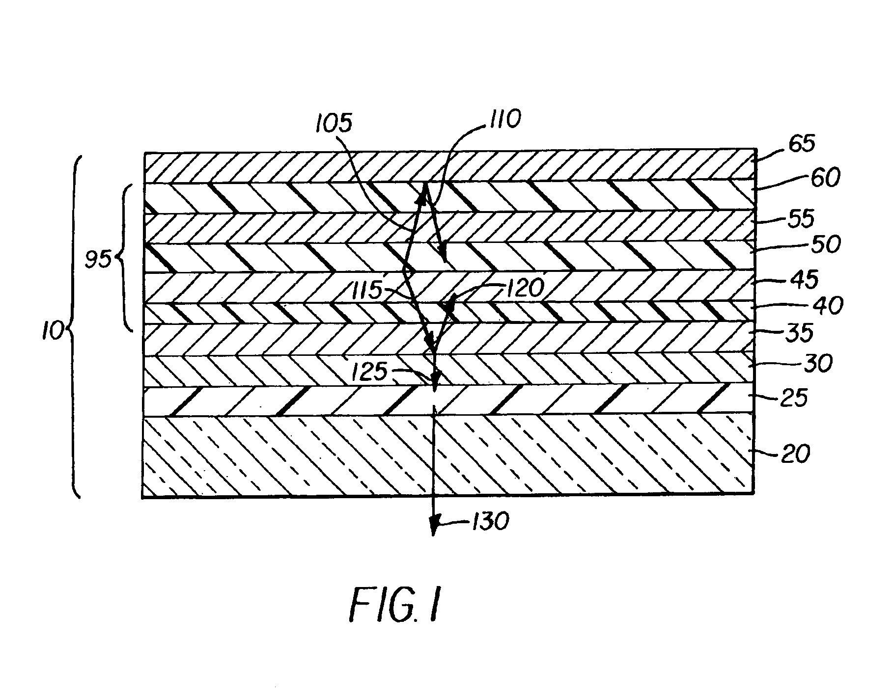
[0134]OLED devices #1, #2, and #3 were constructed in the following manner.

[0135]Substrates coated with 80 nm ITO were sequentially ultrasonicated in a commercial detergent, rinsed in deionized water, and degreased in toluene vapor. These substrates were treated with oxygen plasma for about one minute and coated with 1 nm fluorocarbon layer by plasma assisted deposition of CHF3. These substrates were loaded into a deposition chamber for organic layers and cathode depositions.

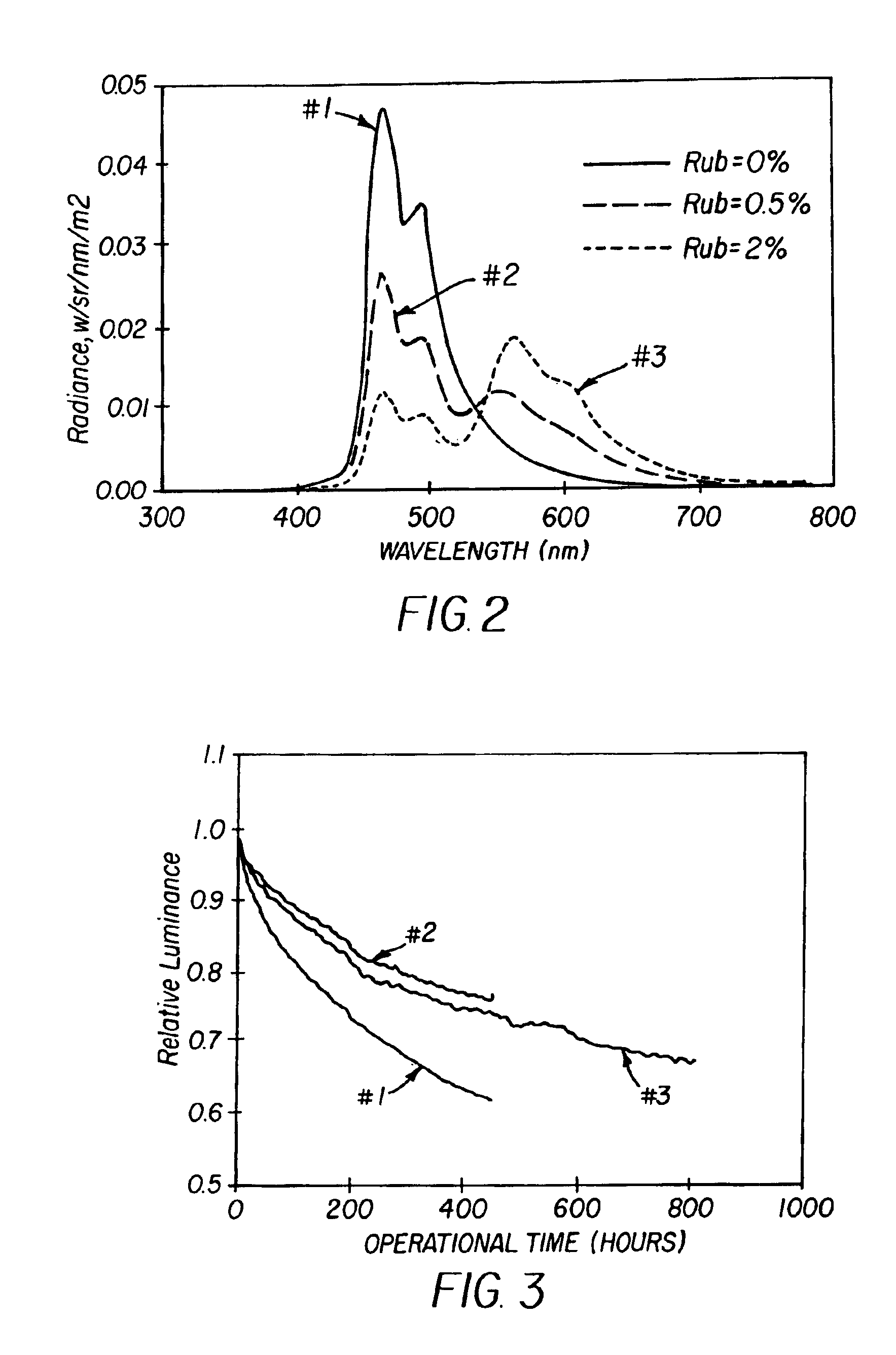
[0136]The devices of Example 1 were prepared by sequential deposition of 150 nm NPB hole-transport layer (HTL) doped with various amounts of rubrene, 20 nm blue emission layer (EML) comprising ADH host with 1.5% TBP blue dopant, 35 nm AIq electron-transport layer (ETL), and 100 nm Mg:10% Ag alloy as the cathode. The above sequence completed the deposition of the OLED device. Device #1 had no rubrene doping into the HTL; device #2 had 0.5% of rubrene doped into the HTL; and device #3 had 2% rubrene doped into HTL...


PUM

PropertyMeasurementUnit
reflectivityaaaaaaaaaa
optical densityaaaaaaaaaa

Abstract

A stabilized OLED device for emitting light of a specific color includes a metallic anode and a metallic cathode spaced from the metallic anode. The device also includes a light-emitting layer including a host and a dopant, the dopant selected to produce light having a spectrum including light of the specific color, and a stabilizer provided in one of the device layers which improves the useful lifetime of the OLED device, wherein the stabilizer has an emission spectrum different from that of the light-emitting layer. One of the electrode layers is semitransparent and the other one is substantially opaque and reflective such that the stabilized OLED device forms a microcavity that emits a narrow band light with the specific color.

Description

CROSS REFERENCE TO RELATED APPLICATIONS[0001]Reference is made to commonly assigned U.S. patent application Ser. No. 09 / 651,624 filed Aug. 30, 2000 by Tukaram K. Hatwar, entitled “White Organic Electroluminescent Devices with Improved Stability and Efficiency” now U.S. Pat. No. 6,696,177 issued Feb. 24, 2004; Ser. No. 09 / 930,050 filed Aug. 15, 2001 by Tukaram K. Hatwar, entitled “White Organic Electroluminescent Devices with Improved Efficiency”, now U.S. Pat. No. 6,627,333 issued Sep. 30, 2003; Ser. No. 10 / 191,251 filed July, 2002 by Tukaram K. Hatwar, entitled “White Organic Light-Emitting Devices Using Rubrene Layer”, now U.S. Pat. No. 6,720,092 issued Apr. 13, 2004; and Ser. No. 10 / 346,424 filed Jan. 17, 2003 by Yuan-Sheng Tyan et al., entitled “Microcavity OLED Devices”; the disclosures of which are incorporated herein by reference.FIELD OF THE INVENTION[0002]The present invention relates to organic electroluminescent (EL) devices. More specifically, the present invention relat...

Claims


Application Information

Patent Timeline
Patent Type & Authority Patents(United States)
IPC IPC(8): H01L51/52H01L51/50H01L27/32H01L27/28
CPCH01L51/5036H01L51/5265H01L51/5048H01L27/322Y10S428/917H10K59/38H10K50/125H10K50/14H10K50/852H05B33/26H05B33/20H05B33/22
Inventor TYAN, YUAN-SHENGHATWAR, TUKARAM K.SHORE, JOEL D.FARRUGGIA, GIUSEPPE
Owner GLOBAL OLED TECH
Why Eureka
Try Eureka