
Electromagnetically responsive heating apparatus for vaporizer

a heating apparatus and vaporizer technology, applied in the field of vapor generators, can solve the problems of large heating element surface area, large space occupation, and inconvenient use of vapor generation methods, and achieve the effects of reducing resistive electrical power loads, reducing resistance electrical power loads, and rapid vapor concentration levels

Inactive Publication Date: 2005-06-14
AMERICAN STERILIZER CO
View PDF28 Cites 50 Cited by
  • Summary
  • Abstract
  • Description
  • Claims
  • Application Information

AI Technical Summary

Benefits of technology

[0014]One advantage of the present invention is that a high output of sterilant vapor is achieved.

Problems solved by technology

Again, the presence of water droplets is not beneficial, as they can shield microbes and prions from the peroxide vapor.
Such vapor generation methods have disadvantages when large quantities of vapor are desired or vapor is needed at short notice.
The large heating element surface area, however, takes up considerable space.
Thus, it takes some time to heat the large volume of water to steam temperature in order for steam generation to begin.
It is expensive to maintain a supply of over 100° C. water ready for a demand.
The capacity of the vaporizer is limited in a number of ways.
First, the vaporization process creates a pressure increase, reducing the flow of the carrier gas through the vaporizer.
Second, to maintain sterilization efficiency, the pressure at which the vapor is generated is limited to that at which the hydrogen peroxide is stable in the vapor state.
Third, the time taken to generate the hydrogen peroxide is dependent on the time taken to heat a surface to the vaporization temperature of hydrogen peroxide.
However, the carrier gas tends to cool the heating surface, disrupting the vaporization process.
However, the use of multiple vaporizers adds to the cost of the system and requires careful monitoring to ensure that each vaporizer is performing with balanced efficiency.
None of these solutions addresses the initial warm up time needed for raising the temperature of the vaporizer to the vaporization temperature.

Method used


Image

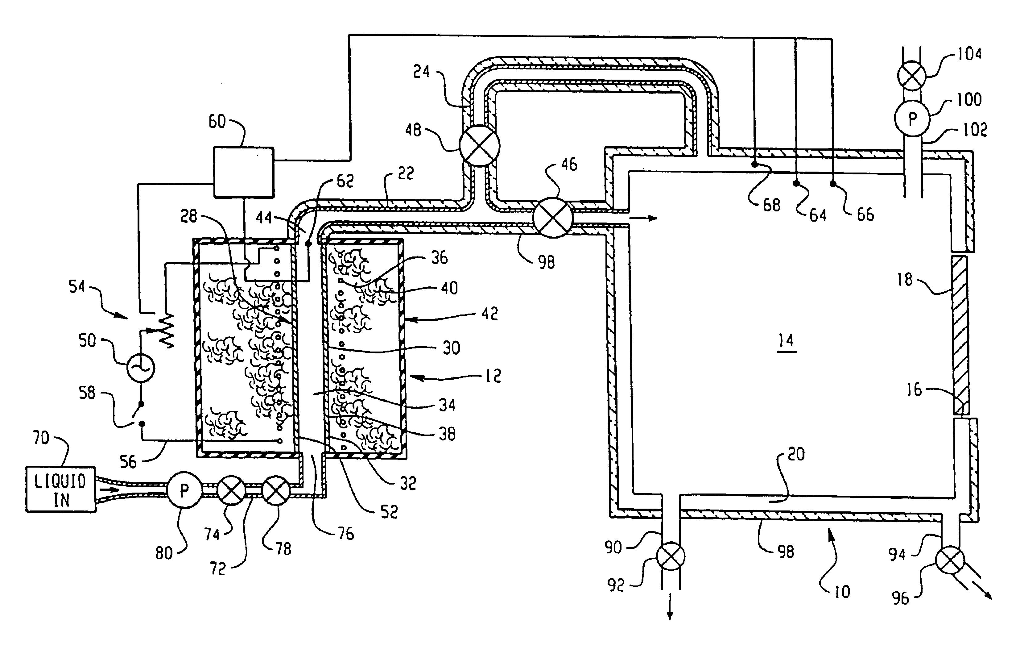
  • Electromagnetically responsive heating apparatus for vaporizer
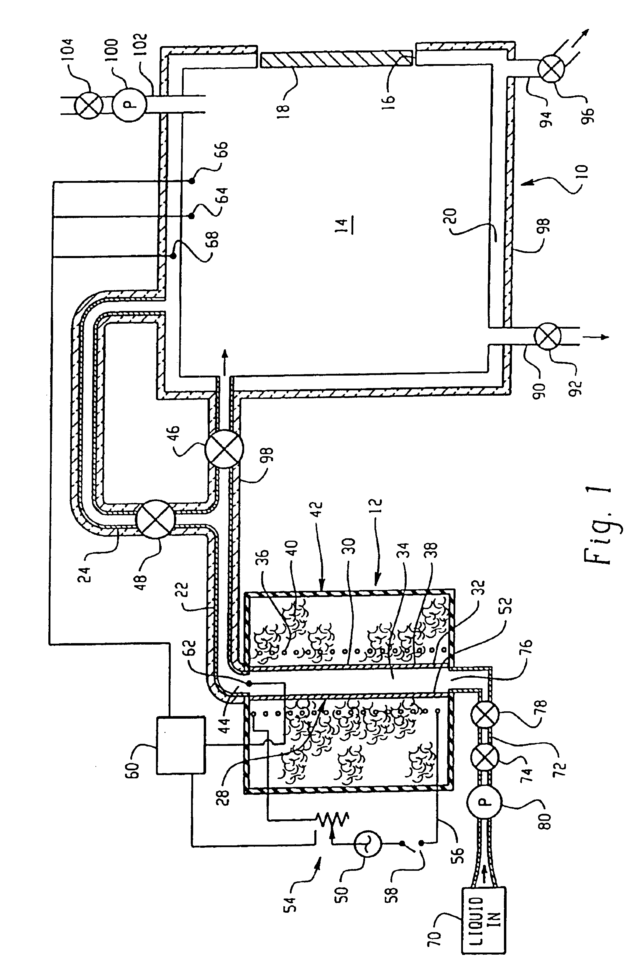
  • Electromagnetically responsive heating apparatus for vaporizer
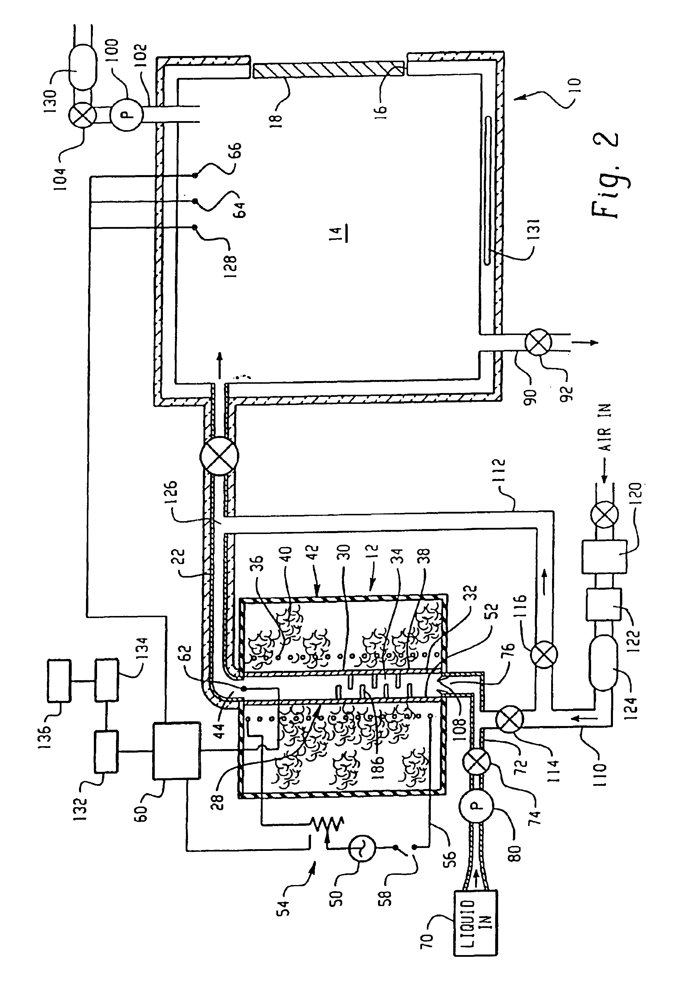
  • Electromagnetically responsive heating apparatus for vaporizer

Examples


example 1

[0128]heating tube: geometry: cylindrical[0129]wall thickness=5 mm[0130]material: resin bonded graphite

(skin depth)(square root of frequency)=δ√{square root over (f)}=1.592

[0131]where δ is the skin depth, and f is the frequency of the electromagnetic radiation applied to the heating tube of Example 1. At a frequency of f=101.4 kHz, the applied electromagnetic radiation will have decreased to 1 / e its initial value within the wall thickness of tube 30 (i.e., 5 mm). To energize electromagnetically responsive material in the insert, electromagnetic radiation of a frequency (f1) less than 101.4 kHz should be used. In this regard, a frequency (f1) less than 101.4 kHz will result in a skin depth greater than the 5 mm wall thickness of tube 30. Accordingly, the emitted radiation has a wavelength that allows propagation through tube 30, and will impinge directly on electromagnetically responsive material in insert 180. Thus, insert 180 is heated directly by induction, rather than by conducti...


PUM


Abstract

A vaporizer heating apparatus is comprised of electromagnetically responsive material and electrically non-conductive material. A antimicrobial fluid to be vaporized, such as water or hydrogen peroxide solution, is supplied to the heating apparatus where it is converted to a vapor. In one embodiment of the present invention, electromagnetically responsive material particulate is embedded into the electrically non-conductive material. In another embodiment of the present invention, a microwave generator is used to produce heat.

Description

RELATED APPLICATIONS[0001]This application is a continuation-in-part of U.S. application Ser. No. 10 / 167,910, filed Jun. 12, 2002, now U.S. Pat. No. 6,734,405, and is hereby fully incorporated herein by reference.FIELD OF THE INVENTION[0002]The present invention relates generally to a vapor generator. It finds particular application in conjunction with steam and hydrogen peroxide vapor systems used in connection with medical device disinfection and sterilization and in the sanitation, disinfection, and sterilization of rooms, buildings, large enclosures, and bottling, packaging, and other production lines and will be described with particular reference thereto. It should be appreciated, however, that the invention is also applicable to other chemical vaporization systems such as those employing other peroxides, peracids, and the like.BACKGROUND OF THE INVENTION[0003]A variety of microbial decontamination processes employ sterilizing vapors, such as steam or a mixture of water vapor ...

Claims


Application Information

Patent Timeline
IPC IPC(8): A61L2/00A61L2/04A61L2/07A61L2/20A61L2/26A61L2/24F22B1/00F22B1/28H05B6/02H05B6/10
CPCA61L2/07A61L2/208A61L2/24H05B6/108B24B49/105F22B1/281F22B1/282A61L2202/122A61L2202/24A61L2202/15
Inventor CENTANNI, MICHAEL A.HILL, AARON L.ZELINA, FRANCIS J.
Owner AMERICAN STERILIZER CO
Learn More