Miniaturized opto-electronic magnifying system

a technology of optoelectronic magnifying system and optical lens, which is applied in the field of miniaturized optoelectronic magnifying system, can solve the problems of not enduring the test of time, difficult use of simple microscope of leeuwenhoek, and many times nearly impossible, and achieves the effect of lowering cost and low cos

Inactive Publication Date: 2005-06-14
SMITHS DETECTION
View PDF10 Cites 15 Cited by
  • Summary
  • Abstract
  • Description
  • Claims
  • Application Information

AI Technical Summary

Benefits of technology

[0021]The miniaturized opto-electronic magnifying system of this invention eliminates the need to look through a microscope eyepiece and objective lens system or to incur the significant cost of a video camera coupled to a compound microscope system. Instead, the magnified electronic image is seen solely on the monitor screen without using an associated compound microscope. The system alone provides significant benefits in the form of very small, low cost magnifying systems such as inverted microscopes and the like, for viewing insects, soil, plants and minerals. When coupled with other sensing technologies such as FT-IR or Raman spectroscopy, even more dramatic benefits result from seeing samples that are being analyzed, such as defects i...

Problems solved by technology

Although Leeuwenhoek's single-lens microscope produced higher resolution and better image quality than the compound microscope, it did not withstand the test of time.
This made Leeuwenhoek's simple microscope difficult, and many times nearly impossible, to use.
People requiring corrective eyeglasses often have difficulty using eyepiece lenses.
Eyepiece magnifications range from 5 to 20 times, and since the eye must be placed closer to the lens of a high magnification eyepiece, higher magnification eyepieces are difficult to use.
These cameras are very e...

Method used


Image

  • Miniaturized opto-electronic magnifying system
  • Miniaturized opto-electronic magnifying system
  • Miniaturized opto-electronic magnifying system

Examples


Embodiment Construction

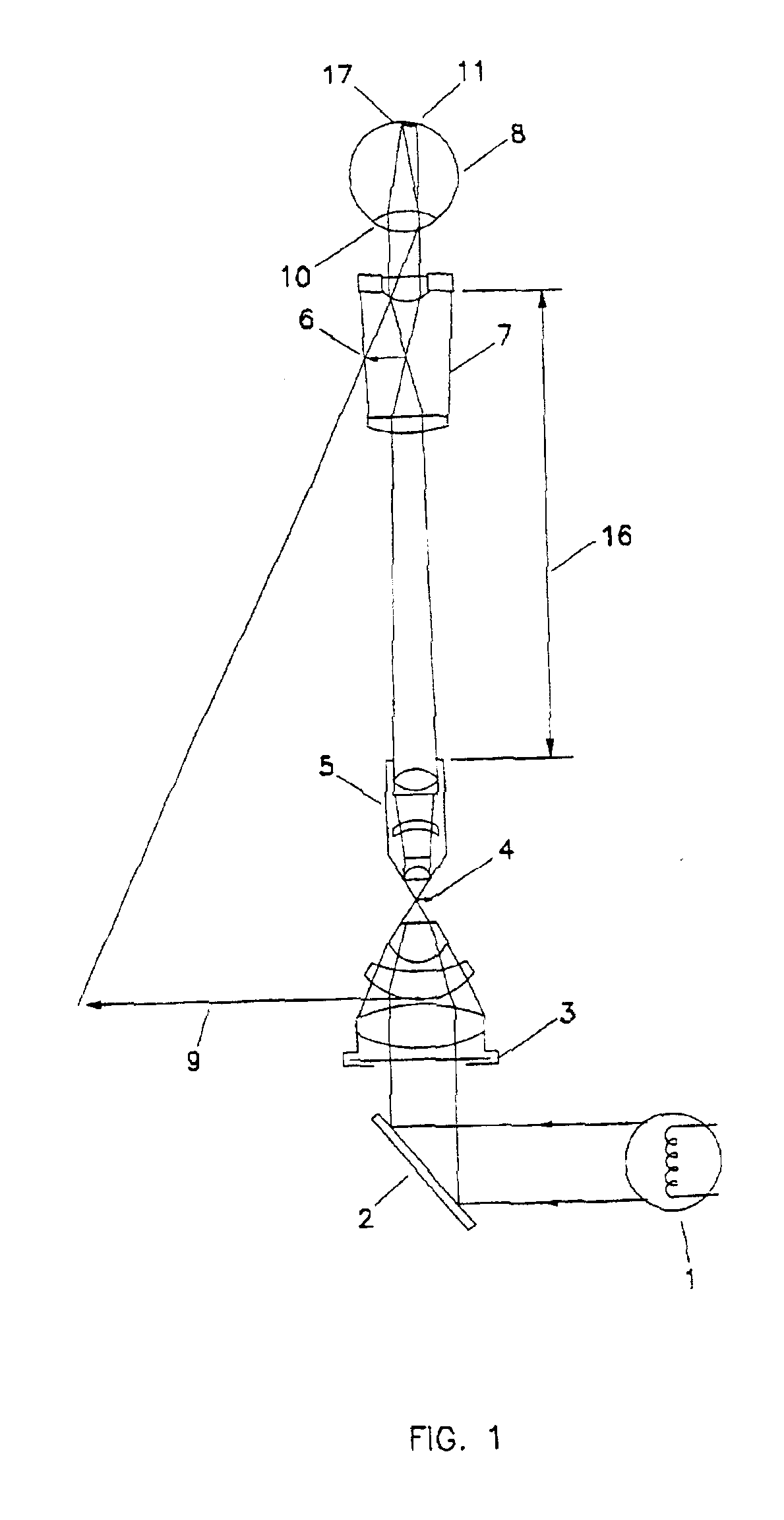
[0035]FIG. 1 shows the principal elements of a conventional compound light microscope used for direct viewing of an optically magnified image. The conventional compound light microscope consists of an illumination source 1, a mirror 2 directing the light into the condenser lens 3 that directs the light to illuminate an object 4. Objective lens 5 projects a real image 6 of the illuminated object into an eyepiece lens 7, eye 8 views a virtual image 9 and an eye lens 10 forms a real image 11 of the object on the retina 17.

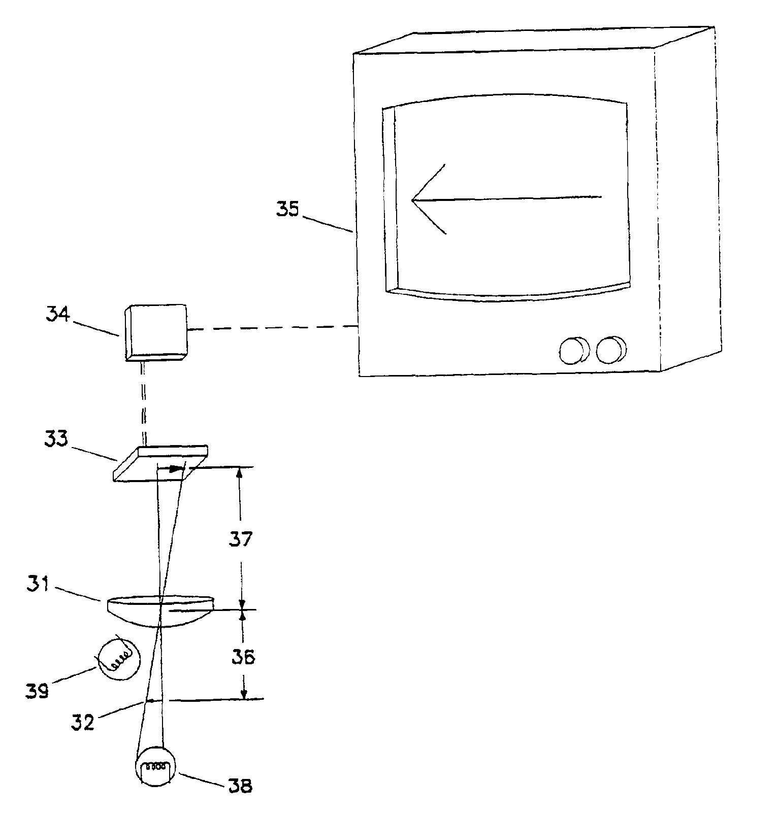
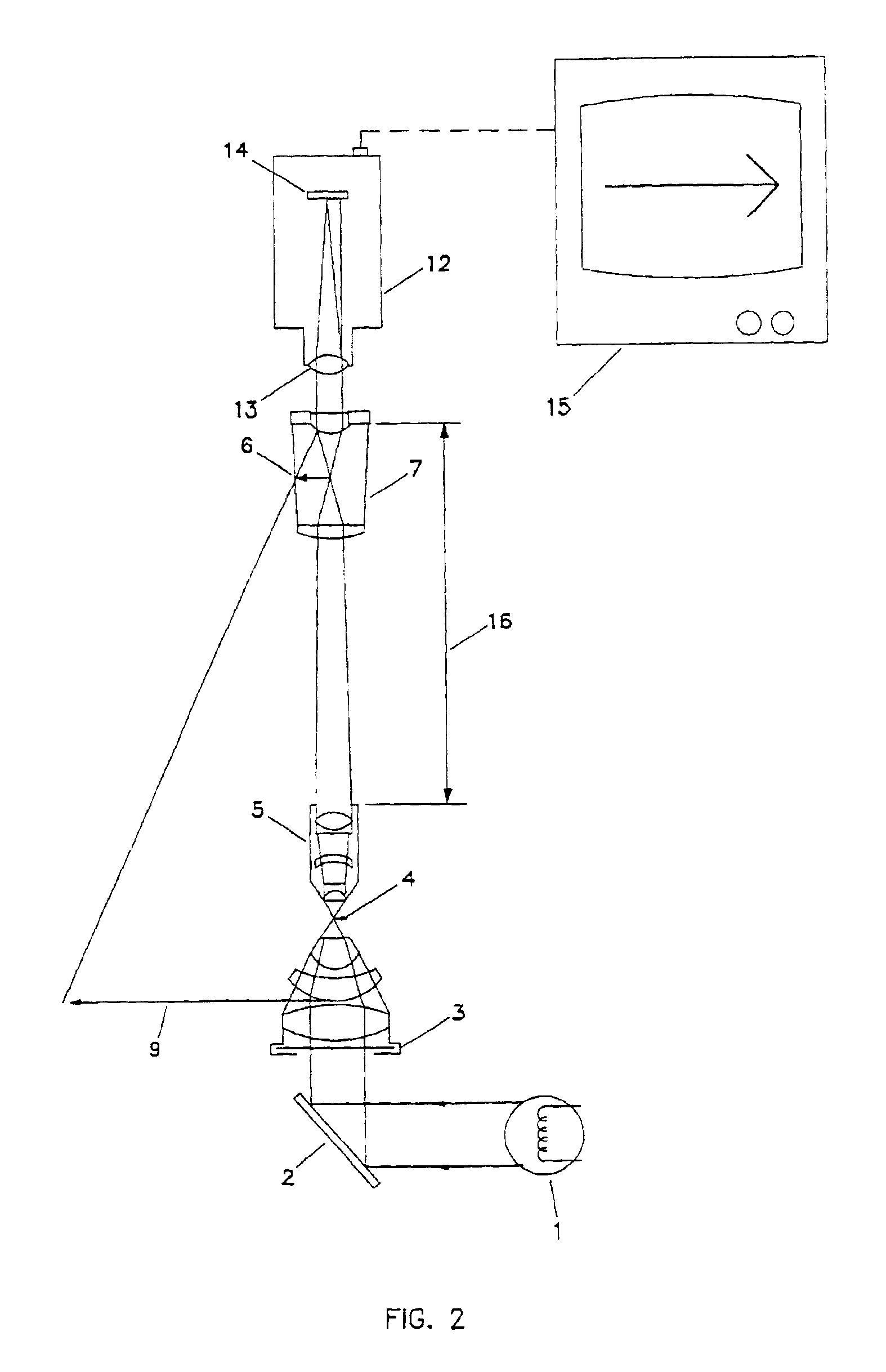
[0036]The present art for converting a compound light microscope into a system for electronic imaging, shown in FIG. 2, is to replace the eye 8, of FIG. 1, with a video camera 12 consisting of a lens 13 and an electronic imaging element 14. The video camera is usually mounted in a separate port to retain normal direct viewing through conventional eyepiece lenses. The electronic image is displayed on a video-display screen 15.

[0037]While compound light microscopes have...


PUM


Abstract

An opto-electronic image magnifying system. The magnifiying system includes: a light source (38, 39) which illuminates an object to be viewed; a miniaturized opto-electronic magnifier module (MOM), made of a lens (31) and a photodetector array (32), which receives the light from the illuminated object; an electronic circuit (34) which receives the signal from the MOM; a video-monitor (35) which receives the magnified signal from the electronic circuit and displays the image. The opto-electronic image magnifying system allows for small objects or features of small objects to be observed in which historically compound microscopes or specialized optical viewing systems were required to observe the small objects.

Description

RELATED CASES[0001]Applicant hereby claims the benefit of their copending provisional application Ser. No. 60 / 112,172, filed Dec. 14, 1998.FIELD OF THE INVENTION[0002]This invention relates to the ever-increasing need in industry, commerce, and education to observe small objects or very small features of objects and to characterize those objects and or features. Historically, such observations have been made on compound microscopes or specialized optical viewing systems.BACKGROUND OF THE INVENTION[0003]Leeuwenhoek founded the science of microbiology in about 1700 using a single-lens microscope. His bead of glass had a magnification of 266 times. Fifty years earlier the compound microscope had been discovered. Although Leeuwenhoek's single-lens microscope produced higher resolution and better image quality than the compound microscope, it did not withstand the test of time. The compound microscope, with objective and eyepiece lens systems, became the standard for all modern light mic...

Claims


Application Information

Patent Timeline
IPC IPC(8): G02B21/00G02B21/36
CPCG02B21/361G02B21/0008
Inventor REFFNER, JOHN A.STING, DONALD W.
Owner SMITHS DETECTION
Why Eureka
Try Eureka