
Modular school building system

Inactive Publication Date: 2005-06-21
TURNKEY SCHOOLS OF AMERICA
View PDF34 Cites 19 Cited by
  • Summary
  • Abstract
  • Description
  • Claims
  • Application Information

AI Technical Summary

Benefits of technology

[0016]In another aspect, the invention is a system for constructing buildings with a modular preassembled frame with a roof portion movable between a flat and a pitched position. The system includes a lift assembly that moves the roof portion between the flat position and the pitched position and anchor assemblies that secure the frame to a building foundation. The system also includes a plurality of fastening devices that secure the modular frame in the flat and in the pitched positions. The system in the flat position is sized so as to fit under standard highway overpasses and bridges and is thereby transportable over the road.
[0018]The region defined between the upper roof in the pitched configuration and the collar creates a dead air space that both increases the insulative properties of the completed building and provides a reservoir of air to reduce the demands on the HVAC system.

Problems solved by technology

While ground up construction offers the advantage that a school can be thereby designed and built specifically for the requirements of a particular building location and client, this specificity incurs significant costs in architect's and approval fees and time.
With the rapidly changing populations, particularly of school age children, that many portions of the country are experiencing, a four year lag time from request to build a new school building until it is ready for use imposes a significant burden to the schools and the children using them.
While convenient, the lightweight construction and size of portables presents several drawbacks to their use as school buildings.
They generally employ a limited amount of insulation in the walls and roof and are often placed directly on a wood foundation.
Thus, the insulative capabilities of a portable are generally lower and the associated heating and cooling costs are generally higher than for a better-insulated permanent building of comparable size.
In addition, the light structure and the typical manner of joining the two separate sections of typical portables makes the portable buildings not as structurally durable over time.
They tend to develop creaky floors and windows and doorframes that distort and make the opening and closing of the windows and doors problematic.
The joint between the two sections of the portable is a potential source of drafts, dirt, and pests and also structural flexing.
The requirement for a portable to fit under overpasses and bridges means that, in practice, the overall height of a typical portable is limited to approximately 12 feet.
With a limited footprint and a ceiling that is typically no more than 9 feet high, the interior volume of a portable building is limited.
Excessive concentration or accumulation of carbon dioxide, dust, pollen, particulates, or noxious vapors are a known health hazard, particularly around children.
The limited volume of air per person of a portable building places significant demands on the building's HVAC system to provide fresh air to the inhabitants.
Another disadvantage of typical portables is the flat roof profile itself.
The lack of a pitch to the roof profile allows a significant amount of snow, rainwater, dirt, and debris to accumulate on the rooftop.
This imposes a significant weight load on the roof.
In addition, accumulated water and debris can attack the roofing materials leading to leaks in the roof appearing prematurely.
Also, since the roof is generally multi-layered, a leak in the outer layer will allow water to ingress, however the water may migrate laterally within the layers of a flat roof so that a water leak into the interior of the building is not necessarily immediately below the external break in the roofing material.
This makes locating a leak source and repairing it more difficult.
It can be appreciated that the thermal insulation factor of a portable with a flat roof surface in relative proximity to the interior ceiling is inferior in comparison to that of a permanent structure with a pitched roof profile and an enclosed dead air space between the roof surface and the interior ceiling surface, assuming comparable insulation materials in the two structures.
Many portable building designs lack provision for securely fastening the building to the foundation.
The anchoring methods utilized by many portable designs incorporates metal strapping or anchors shot into the foundation that are typically not strong enough to inhibit building uplift in an extreme stress event.

Method used


Image

  • Modular school building system
  • Modular school building system
  • Modular school building system

Examples


Embodiment Construction

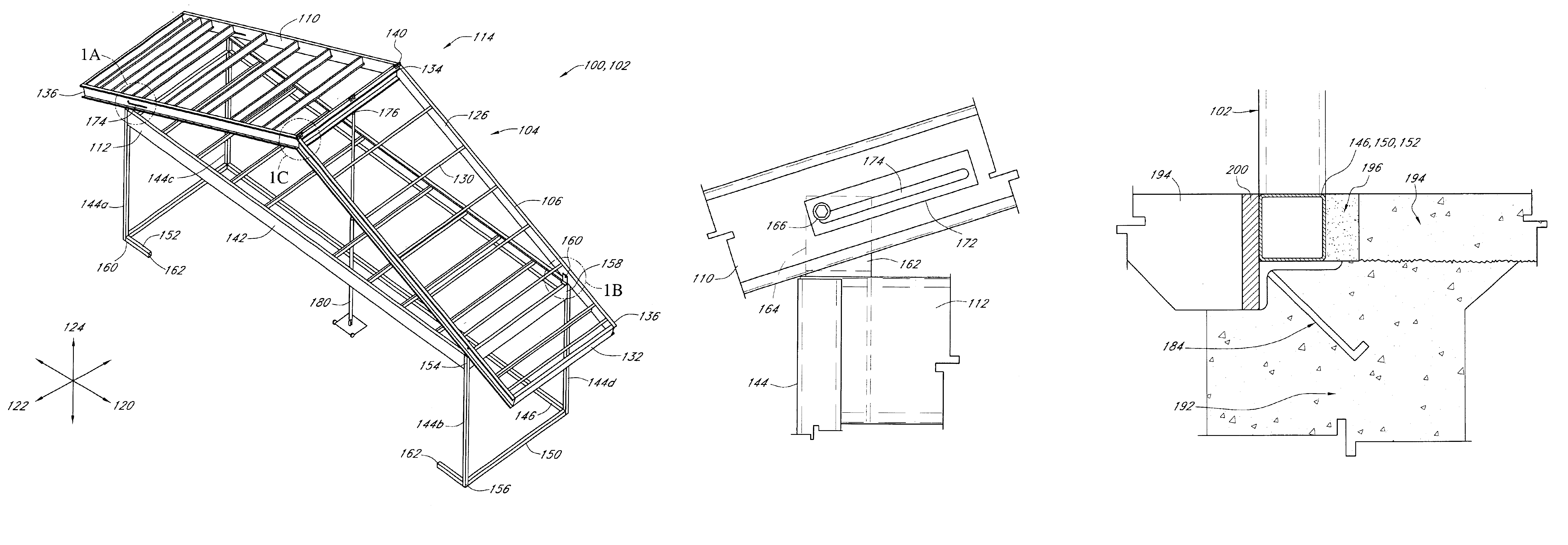
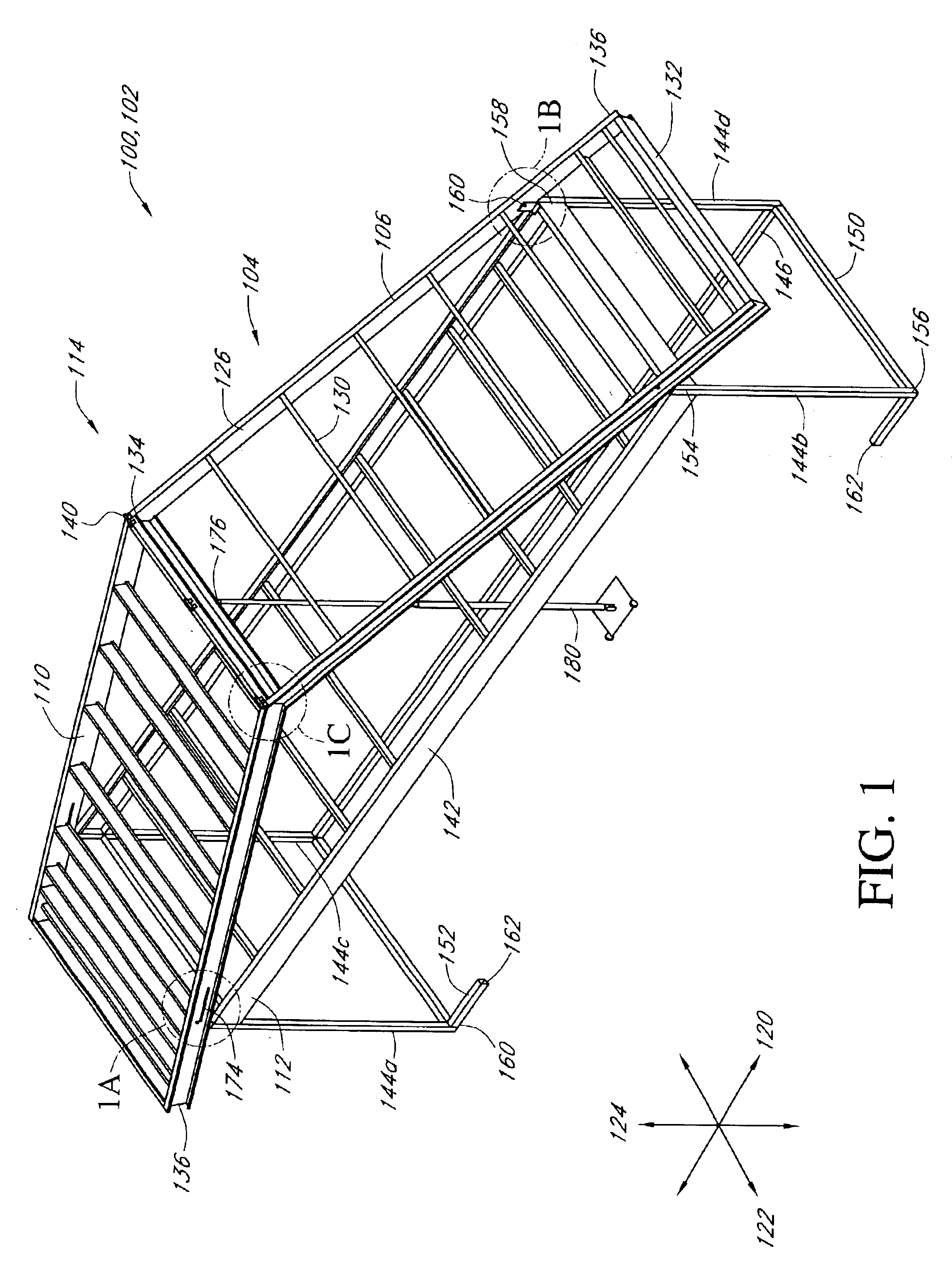
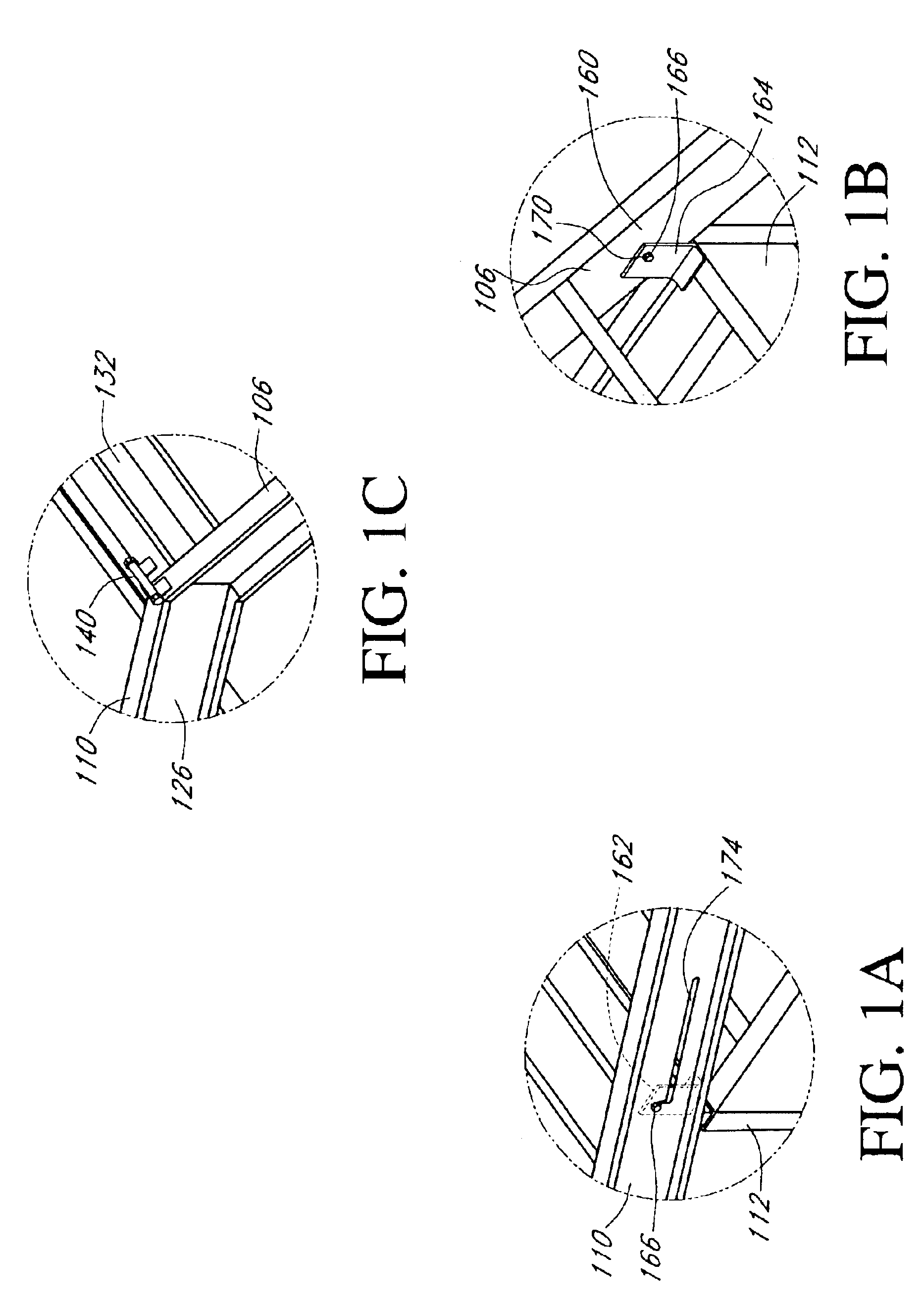
[0034]Reference will now be made to the drawings wherein like numerals refer to like parts throughout. FIG. 1, along with details A, B, and C are isometric views of a modular school building system 100 comprising a frame module 102. The modular school building system 100 provides a substantially preassembled and preapproved design for constructing a permanent school building with a pitched roof. The modular school building system 100 is transportable over the road on standard trucks.

[0035]The frame module 102 of this embodiment is generally rectangular and constructed of steel c-channels and comprises a collar 112 and an upper roof 104. The upper roof 104 is movable between a pitched configuration 114 illustrated in FIG. 1 and a flat configuration 116 illustrated in FIG. 10. The pitched configuration 114 provides a sloping roof profile to the frame module 102 so that, when the frame module 102 is connected with other frame modules 102 and provided with other materials to comprise a ...


PUM


Abstract

A substantially preassembled modular frame system for erecting permanent school buildings. The system design, materials, and construction have been pre-approved by state inspectors. The system provides a roof that is extensible from a low position that is configured to permit the system to be transported on highways and fit under common overpasses and bridges to a pitched position that provides a sloped roof profile to improve insulation factors of completed buildings and better shed rain, snow, and debris. The system includes anchor assemblies that are rigidly connected to the frame to inhibit uplift forces acting on the building from distorting or dislodging the building from the foundation. The system also includes preassembled wall panels and a convenient mechanism for emplacing and securing the wall panels within the modular frames.

Description

RELATED APPLICATIONS[0001]This application is a continuation of U.S. Pat. No. 6,519,900 which issued Feb. 18, 2003 which corresponds to U.S. application Ser. No. 09 / 616,486 filed Jul. 14, 2000 and claims the benefit of U.S. Provisional Application No. 60 / 215,515 entitled Modular School filed Jun. 30, 2000.BACKGROUND OF THE INVENTION[0002]1. Field of the Invention[0003]The present invention relates to the field of building construction and, in particular, to a modular system for assembling school buildings.[0004]2. Description of the Related Art[0005]School construction has typically proceeded in a manner very similar to that of traditional residential home construction. An architect first drafts a set of plans for the building. The plans are then checked and approved by the client and the responsible regulatory agency. The design, drafting, and approval process typically takes a year or so, particularly as changes are often required by the client or the approval entity. Once the pla...

Claims


Application Information

Patent Timeline
IPC IPC(8): E04B7/24E04B7/00E04B1/24E04B7/02
CPCE04B1/24E04B7/026E04B7/24E04B2001/2415E04B2001/249E04B2001/2448E04B2001/2463E04B2001/2484E04B2001/2439
Inventor PIERCE, ALAN
Owner TURNKEY SCHOOLS OF AMERICA
Features
  • Generate Ideas
  • Intellectual Property
  • Life Sciences
  • Materials
  • Tech Scout
  • Unparalleled Data Quality
  • Higher Quality Content
  • 60% Fewer Hallucinations
Learn More