Shaftless gyrostabilizer for aerial platforms

a technology of gyrostabilizer and aerial platform, which is applied in the direction of instruments, special purpose vessels, vessel construction, etc., can solve the problems of occupying valuable space, affecting the stability of the body, and requiring the rotation of the entire disc, so as to achieve unlimited flexibility

a technology of gyrostabilizer and aerial platform, which is applied in the direction of instruments, special purpose vessels, vessel construction, etc., can solve the problems of occupying valuable space, affecting the stability of the body, and requiring the rotation of the entire disc, so as to achieve unlimited flexibility

US6907800B1Inactive Publication Date: 2005-06-21INMAN WILLIAM E

Image

  • Shaftless gyrostabilizer for aerial platforms
  • Shaftless gyrostabilizer for aerial platforms
  • Shaftless gyrostabilizer for aerial platforms

Examples


second embodiment

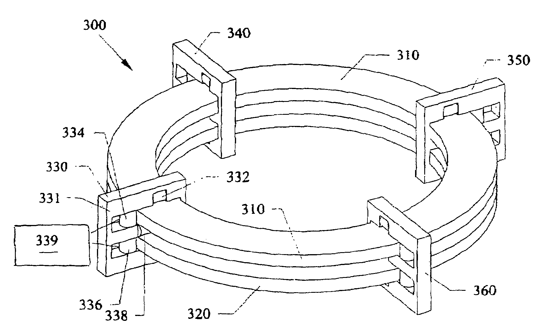
[0046]the present invention consists of a first circular track having a first set of balls that are alternatingly made of ferrous and non-ferrous material. The first circular track is adjacently stacked on a second circular track having a second set of balls that are also alternatingly made of ferrous and non-ferrous material. In combination with the first and second circular tracks is a means for moving the first and second track in opposite, counter-revolving directions by electromagnetic propulsion. Electrified magnets are positioned in an efficient and symmetrical pattern on both the first and second circular tracks. When power is applied, the magnets attract the ferrous balls in the desired direction and with a controllable speed to accomplish stabilization of a vehicle or structure which may be subject to vibrations, pitching, yawing, rolling, swaying and the like.

[0047]The ferrous balls of the second embodiment are by definition largely comprised of iron or an iron alloy. Ste...

first embodiment

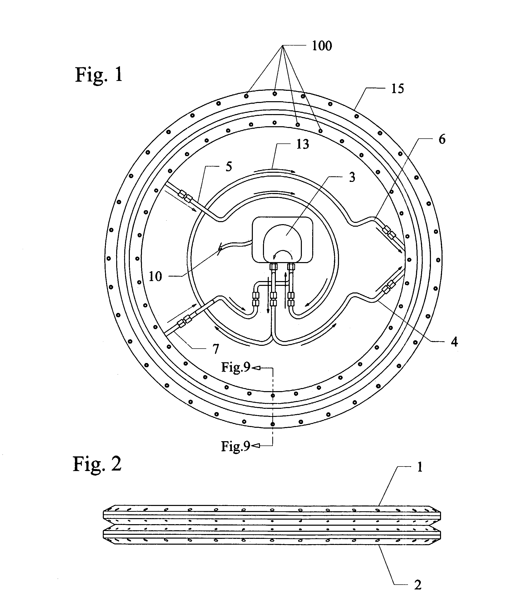
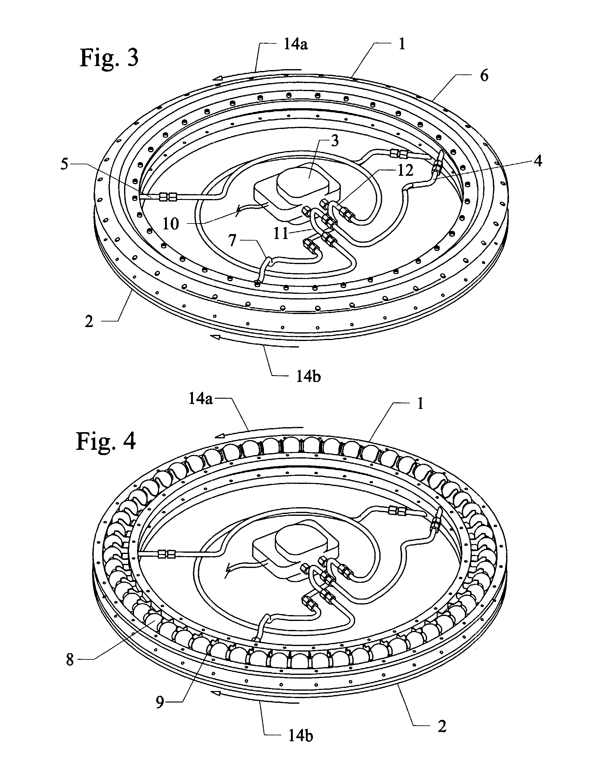
[0065]The embodiment of FIGS. 1–7 can be modified to be used without any ball type masses or any other solid type masses, so that the pressure pump 3 is positioned inside the circular track 1 and only forces different types of fluid simultaneously into the upper gyro drive line 4 and a lower gyro drive line 6. The fluid embodiments can include liquids, gases, combinations thereof, that can operate similar to the

[0066]In a liquid application, the pressure pump can move liquids solely through the two tracks, such as only oil. Alternatively, the pressure pump can move other types of liquids such as water, and the like. The liquid density and mass can be selectively adjusted to achieve various stability effects in this embodiment by using different types and / or mixtures of liquid.

[0067]In a gas state application, the pressure pump can move gasses solely through the two tracks, such as only oxygen, argon, helium, and the like, and combinations thereof. The density and mass of the gases c...


PUM


Abstract

Gyrostabilizer methods and apparatus having simultaneously counter-revolving masses that do not require physical shafts or axles. The stabilizer can have dual counter-revolving concentric rings, or tracks filled with weights such as spherical balls, that are propelled in orbital fashion by fluid pressure or electromagnet propulsion. The rings can include rigid contiguous rings, such as metal, plastic, composites, and the like. Additionally, the rings can include liquids and / or gasses. Still furthermore, the rings can include flexible, bendable contiguous materials, such as chains and ropes. The concentric ring diameters can be a few inches to more than ten (10) feet. Without an axle or shaft the weight of the gyrostabilizer is shifted to the perimeter where most of the momentum is generated at a fraction of the weight of gyrostabilizers that spin on an axle. The gyrostabilizer can dampen unsteadiness such as tremors, vibrations, sway, pitch, roll, and yaw.

Description

[0001]This invention is a Continuation-In-Part of U.S. patent application Ser. No. 09 / 680,495 filed Oct. 5, 2000, now allowed now U.S. Pat. No. 6,568,291.FIELD OF INVENTION[0002]This invention relates to shaftless gyrostabilizers, and in particular to methods and apparatus for stabilizing aerial platforms and vehicles while in motion or hover mode, where the gyrostabilizers control pitching, rolling, yawing and other unsteadiness in aerial platforms and vehicles that have limited or no other inherent controls for self-stabilization, and this invention also is used to dampen tremors, vibrations, swaying in buildings.BACKGROUND AND PRIOR ART[0003]Counter-rotating or oppositely spinning discs, or wheels, mounted on centrally located shafts or axles are known to be used as stabilizers for guided missiles in U.S. Pat. No. 3,193,216; for rotation control of a space vehicle in U.S. Pat. No. 3,424,401; and to suppress oscillation about an axis of a loaded crane in U.S. Pat. No. 3,498,476. I...

Claims


Application Information

Patent Timeline
21 Jun 2005
Publication
US6907800B1
IPC
B64G1/24; B64G1/28
CPC
B64G1/28; B64G1/285; B64G1/286; Y10T74/1221; Y10T74/125; Y10T74/1296; Y10T74/1229
Inventors
INMAN, WILLIAM E.