Filter element and assembly with continuous drain

Active Publication Date: 2005-06-21
PARKER INTANGIBLES LLC
View PDF11 Cites 43 Cited by
  • Summary
  • Abstract
  • Description
  • Claims
  • Application Information

AI Technical Summary

Benefits of technology

[0021]The present invention provides a novel and unique filter assembly and filter element for a crankcase emissions control system. The system can be used continuously to remove oil from blow-by gasses from the e

Problems solved by technology

However, crankcase emission controls have been largely neglected.
Crankcase emissions result from gas escaping past piston rings of an internal combustion engine and entering the crankcase due to high pressure in the cylinders during compression and combustion.
As the blow-by gas passes through the crankcase and out the breather, it becomes contaminated with oil mist.
Some current production diesel engines discharge these crankcase emissions to the atmosphere through a draft tube or similar breather vent contributing to air pollution.
Some of the crankcase emissions are drawn into the engine intake system causing internal engine contamination and loss of efficiency.
The released oily crankcase emissions coat engine sites, such as the inside of engine compartments or chambers, fouling expensive components and increasing costs, such as clean-up, maintenance and repair costs.
The accumulation of the particulates on these components reduces efficiency, performance and reliability of the engine.
Thus, the environmental impact and engine efficiency from

Method used


Image

  • Filter element and assembly with continuous drain
  • Filter element and assembly with continuous drain
  • Filter element and assembly with continuous drain

Examples


Embodiment Construction

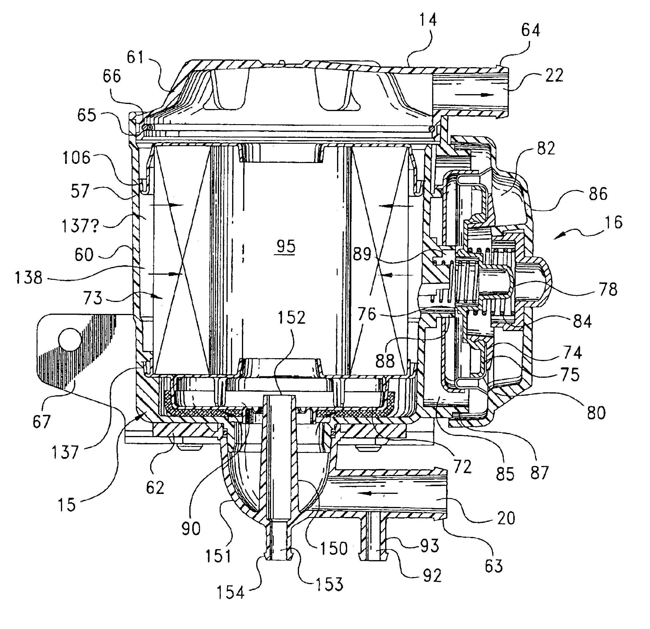
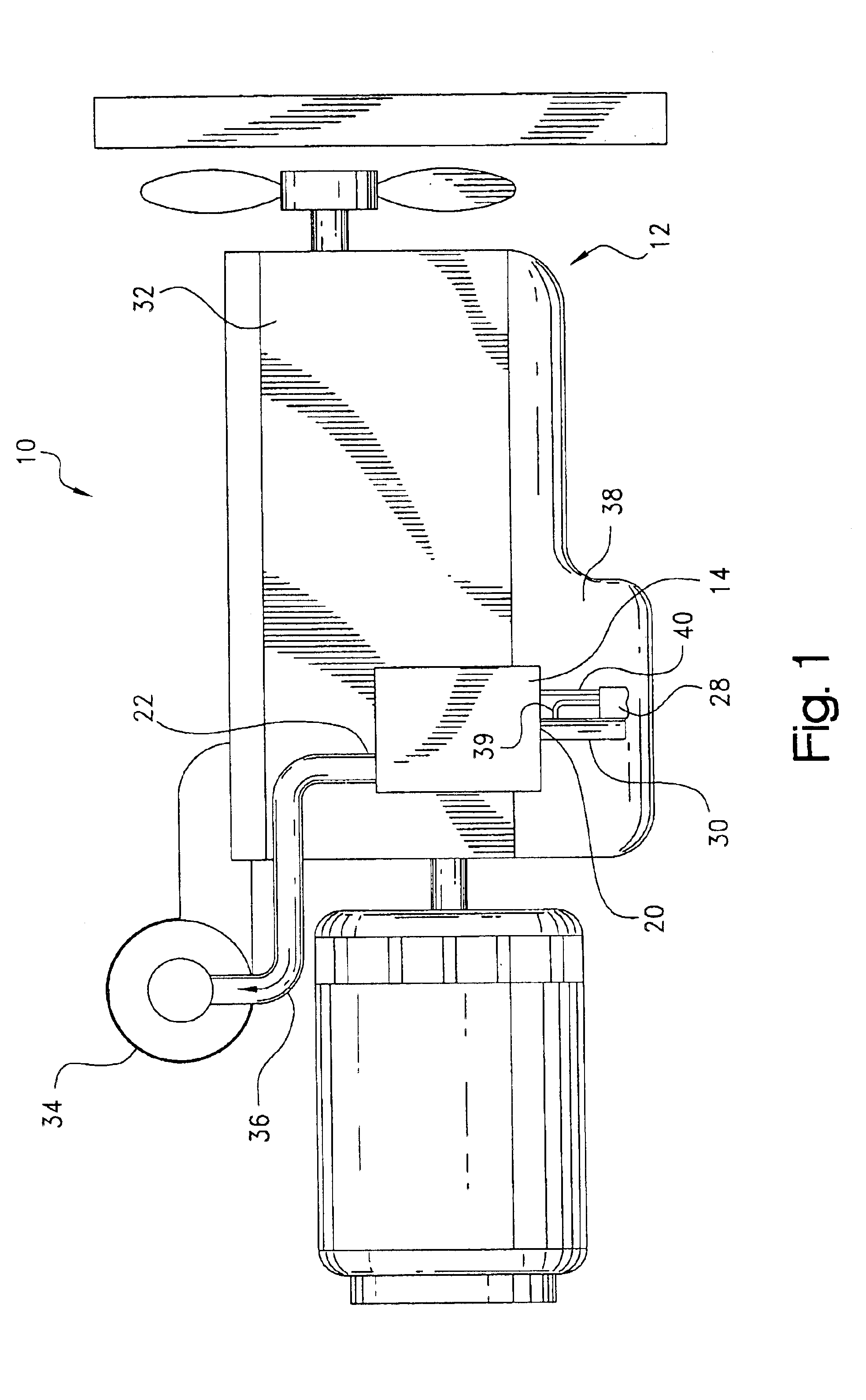
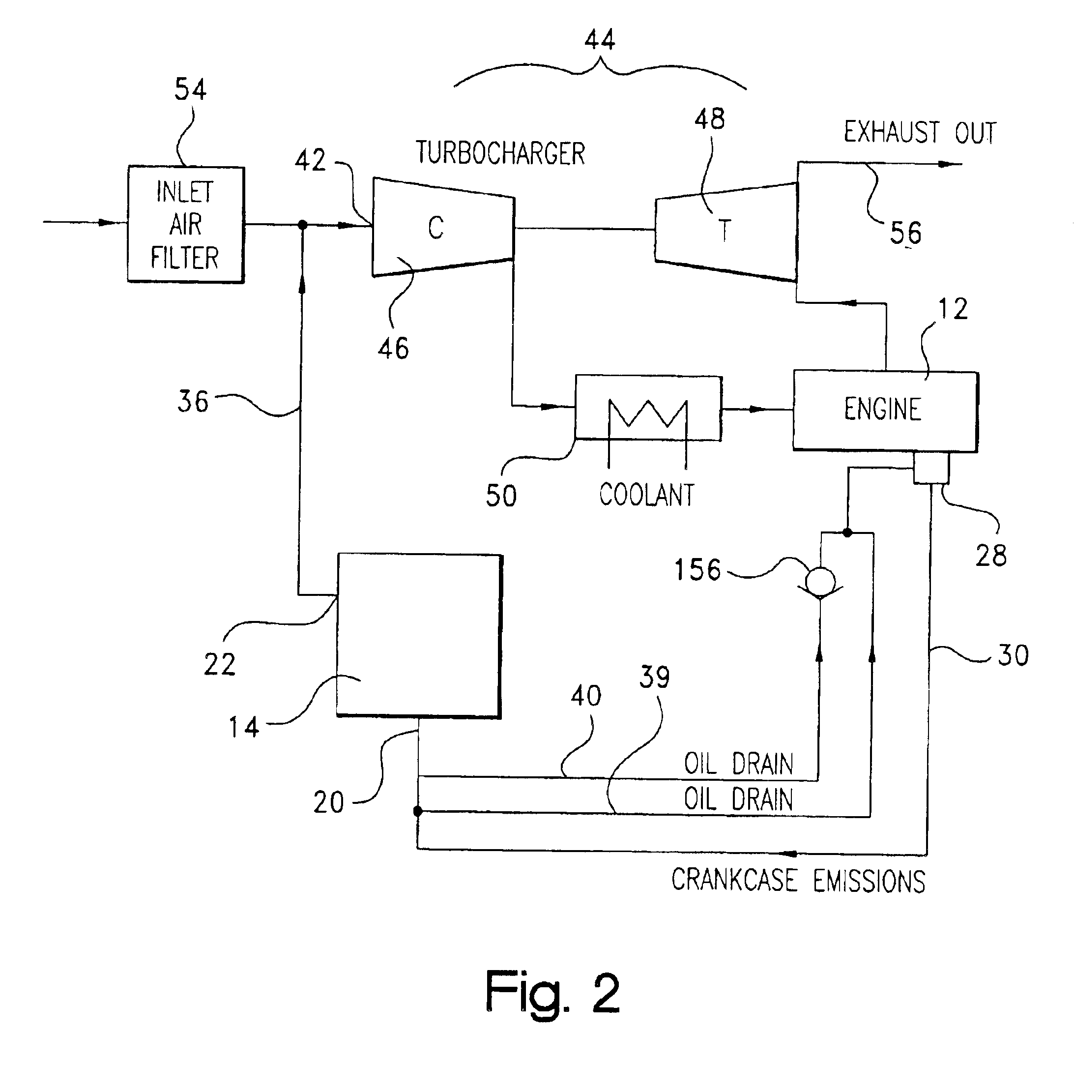
[0034]Referring to the drawings, and initially to FIG. 1, a closed crankcase emission control system is indicated generally at 10. The system includes an internal combustion engine, indicated generally at 12, and an integrated crankcase emission control assembly 14. The integrated crankcase emission control assembly 14 includes a filter assembly, indicated generally at 15, and preferably a pressure regulator, indicated generally at 16, as will be described below.

[0035]The crankcase emission control assembly 14 has a gas inlet 20 and a gas outlet 22. The gas inlet 20 is connected to the engine crankcase breather 28 via an inlet hose 30 and receives contaminated oily gas from the engine crankcase 32. The crankcase emission control assembly 14 separates the contaminated oily gas, agglomerates small particulates to form larger particulates, and filters the large particulates.

[0036]The cleaned crankcase emissions exit from the gas outlet 22 and enter the engine air intake 34 for combusti...


PUM

PropertyMeasurementUnit
Diameteraaaaaaaaaa

Abstract

A closed crankcase emission control assembly for an internal combustion engine includes a filter assembly comprising a housing and a replaceable filter element. The filter element includes a ring of filter media; a first annular end cap sealed to one end of the media ring; a second end cap sealed to another end of the media ring; a cup-shaped valve pan fixed to the second end cap and which together therewith defines a sump container; and an opening with a lip seal in the valve pan which closely receives a standpipe from the housing to allow continuous drainage of oil collected by the filter element. The filter housing includes an inlet port to receive blow-by gasses from the engine crankcase, and an outlet port to provide the substantially oil and particulate free gasses to an induction system (e.g. a turbocharger) and back to the engine crankcase.

Description

CROSS-REFERENCE TO RELATED CASES[0001]The present application claims the benefit of the filing date of U.S. Provisional Application Ser. No. 60 / 441,407; filed Jan. 17, 2003, the disclosure of which is expressly incorporated herein by reference.FIELD OF THE INVENTION[0002]The present invention is directed to a filter element and assembly for a crankcase emission control system. The crankcase emission control system is useful for a heavy internal combustion engine, such as a diesel engine.BACKGROUND OF THE INVENTION[0003]Emission controls for internal combustion engines have become increasingly important as concerns over environmental damage and pollution have risen—prompting legislators to pass more stringent emission control laws. Much progress has been made in improving exhaust emission controls. However, crankcase emission controls have been largely neglected.[0004]Crankcase emissions result from gas escaping past piston rings of an internal combustion engine and entering the cran...

Claims


Application Information

Patent Timeline
IPC IPC(8): B01D46/24F01M13/04F01M13/02F01M13/00F02M25/06F02B29/04F02B29/00B01D46/00
CPCB01D46/0031B01D46/2414B01D46/4272F01M13/022F01M13/04F02M25/06F01M13/023Y02T10/121F01M2013/0438F02B29/0437Y02T10/12
Inventor BURGESS, STEPHEN F.TOMCHAK, THOMAS M.
Owner PARKER INTANGIBLES LLC
Why Eureka
Try Eureka