Apparatus and method for cooling power transformers

a transformer and apparatus technology, applied in the field of transformers, can solve the problems of reducing the efficiency of the transformer, reducing the useful life of the transformer, and high cost to the industry, and achieve the effects of reducing the cost of operation, maximizing the electrical capacity of the transformer, and effective cooling

Inactive Publication Date: 2005-06-21
TRW INC +1
View PDF3 Cites 61 Cited by
  • Summary
  • Abstract
  • Description
  • Claims
  • Application Information

AI Technical Summary

Benefits of technology

[0015]One advantage of the present invention is that it provides a system for effectively cooling the inner workings of a transformer for all atmospheric conditions in order for the transformer to not be subjected to heat which damages its structural integrity and/or its efficiency.
[0016]Still another advantage of the present invention is that the cooling system can use a heat exchanger operated with chillate provided by the use of off-peak energy, thereby decreasing the cost of operations. Yet another advantage is that the heat energy of the transformer can be utilized in providing the energy required

Problems solved by technology

The failure to keep the transformer temperature so regulated can result in failure of the transformer or perhaps the significant reduction of its useful life, each of which results in high cost to the industry due to the need to replace the destroyed transformer units.
Moreover, due to the directly proportional relationship between temperature and electrical resistance, when the temperature of the copper windings in the transformer core increases, the efficiency of the transformer decreases, thereby resulting in a loss of power output (watts) proportional to transformer core heating.
Some prior attempts at controlling transformer temperature have been relatively crude.
First, a “self cooled” level essentially relies on convention currents within the transformers insulating and cooling oil to draw heat away from the core.
While the prior art cooling system shown in F

Method used


Image

  • Apparatus and method for cooling power transformers
  • Apparatus and method for cooling power transformers
  • Apparatus and method for cooling power transformers

Examples


Embodiment Construction

[0029]For the purposes of promoting an understanding of the principles of the invention, reference will now be made to the embodiments illustrated in the drawings and specific language will be used to describe the same. It will nevertheless be understood that no limitation of the scope of the invention is thereby intended. The invention includes any alterations and further modifications in the illustrated devices and described methods and further applications of the principles of the invention which would normally occur to one skilled in the art to which the invention relates. For example, while the illustrated embodiment is a retrofit to an existing system, the inventive cooling system can be incorporated into the design specifications for a newly constructed power transformer array.

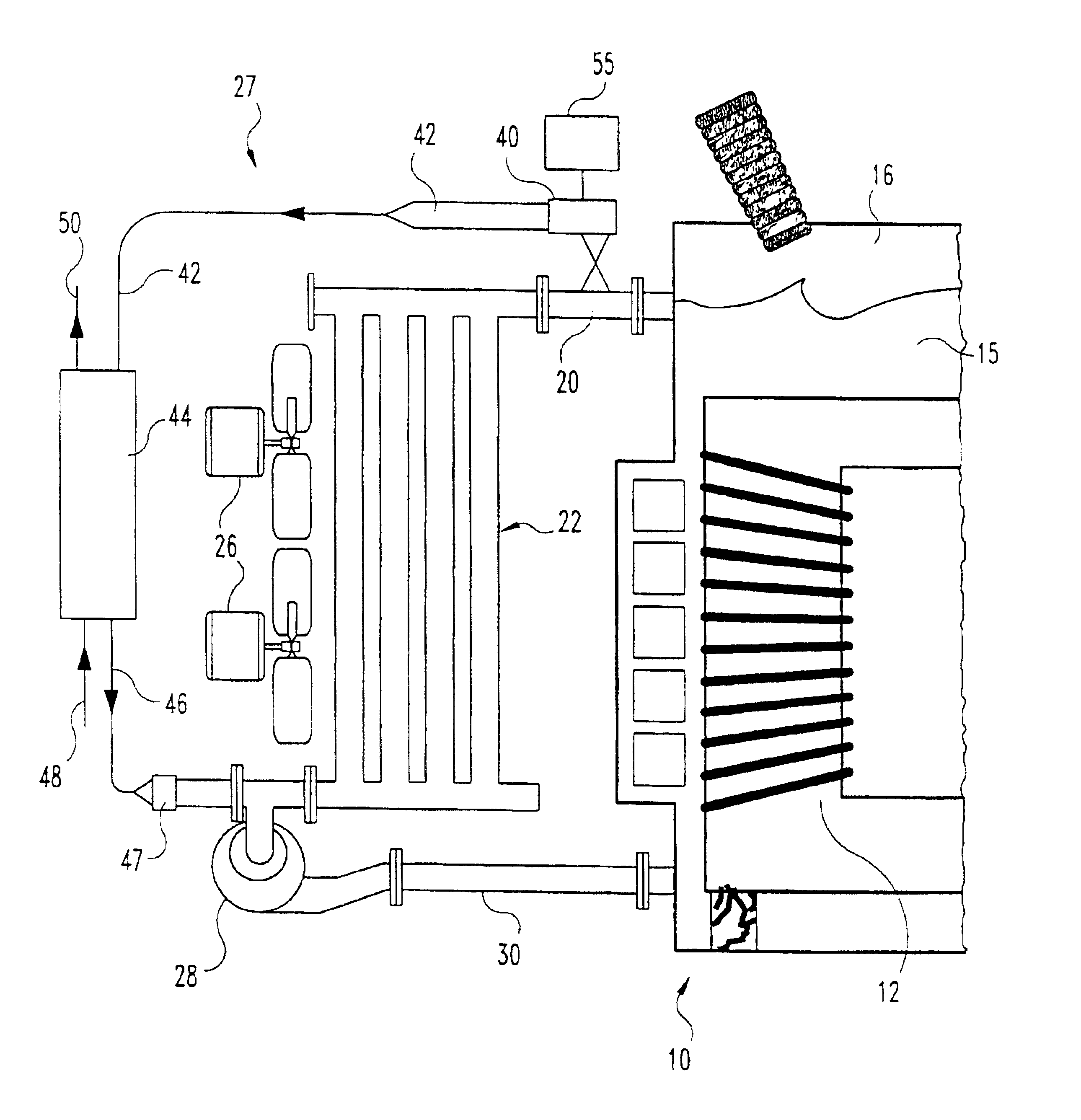
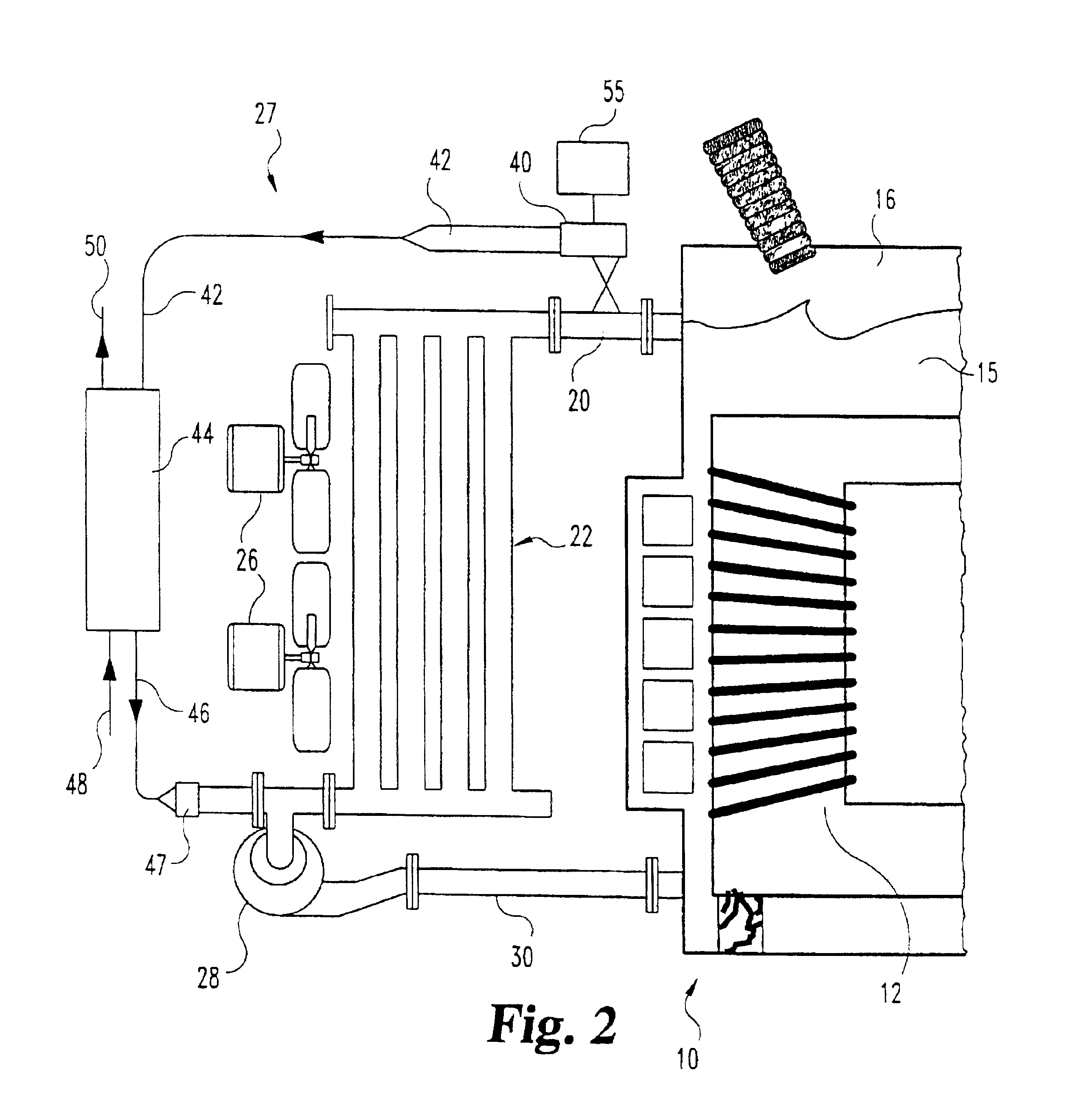
[0030]Referring now to FIG. 2, there is diagrammatically shown selected portions of one embodiment of a transformer cooling system 27 of the present invention. In this embodiment, the transformer and co...


PUM

PropertyMeasurementUnit
Temperatureaaaaaaaaaa
Energyaaaaaaaaaa
Heataaaaaaaaaa

Abstract

A system (27) for reducing the temperature of cooling oil for a power transformer (12) includes a heat exchanger (44) interposed in the cooling oil system. The heat exchanger (44) relies upon a liquid-to-liquid exchange of heat from the heated oil to a coolant flowing through the heat exchanger. In one embodiment, the coolant provided to the heat exchanger is obtained from an absorption chiller (65). Heat energy is provided to the chiller (65) from a heat storage device (80). In a specific embodiment, the heat storage source (80) can be a phase change material device. In a preferred cooling system, a programmable controller (55) determines the activation and operation of the system. The controller (55) can sense transformer or cooling oil temperature to trigger activation. In a preferred embodiment, the controller (55) compares a current temperature history against a temperature profile to anticipate increased cooling requirements. In certain embodiment, excess, off-peak or waste heat from the transformer (12) itself is provided to the heat storage device (80) or to the phase change heat exchanger.

Description

[0001]This application claims the benefit of Provisional application Ser. No. 60 / 166,065 filed Nov. 17, 1999.BACKGROUND OF THE INVENTION[0002]The present invention pertains to transformers, and, in particular, to an apparatus and method for cooling power transformers during use.[0003]Power transformers are employed within power supply systems in order to transform, transmit and distribute electricity for end-user consumption. Transformers are designated by high and low side operating voltages, and sized as to capacity of the volts and amperes being carried. For example, large-size transformers are utilized as transmission transformers, which step up the voltage along the power supply chain, as well as distribution transformers, which step down the voltages for distribution.[0004]One shortcoming of existing transformers is their susceptibility to operational problems associated with high temperatures of operation, both internal and external to the transformers. Typically, in order to...

Claims


Application Information

Patent Timeline
IPC IPC(8): F25B15/00F25B25/00H01F27/10H01F27/12F28D20/02
CPCF25B15/00F25B25/005F28D20/02H01F27/10F25B2333/007F25B2400/24Y10T29/4935H01F27/12Y02B30/62Y02E60/145Y10T29/4902F28D2021/0019Y02E60/14Y02A30/27
Inventor LONGARDNER, ROBERT L.VISNESKY, JR., ANTHONY M.
Owner TRW INC
Why Eureka
Try Eureka