Emissivity probe

Inactive Publication Date: 2005-06-21
DIAMOND POWER INT +1
View PDF36 Cites 3 Cited by
  • Summary
  • Abstract
  • Description
  • Claims
  • Application Information

AI Technical Summary

Benefits of technology

[0008]In accordance with this invention, an emissivity probe for boiler wall monitoring is provided. The device uses a pair of optical guides, with one optical guide facing and receiving infrared radiation from the internal fireball within the boiler interior. The other optical guide is directed to receive radiation reflected from the wall surface. Photo detectors receive light transmitted by the optical guides, and produce an electrical signal output. By comparing the ratio or difference of these outputs, a measure of the degree to which the surface reflects radiation can be developed. Preferably, the probe is sensitive to radiation in the infrared region of the spectrum and over a band of radiation in the wavelength region of 0.4 to

Problems solved by technology

In the operation of large scale combustion devices such as coal burning boilers, there is a continual build up of slag deposits on their internal walls and heat transfer surfaces.
Operating sootblowers causes an efficiency penalty for the boiler when it is not used then at a time when it is actually needed.
Operating cleaning systems based strictly on time or other indirect measures can result in operating the cleaning devices on a schedule which is not optimal.
Although these systems are effective in many ap

Method used


Image

  • Emissivity probe
  • Emissivity probe
  • Emissivity probe

Examples


first embodiment

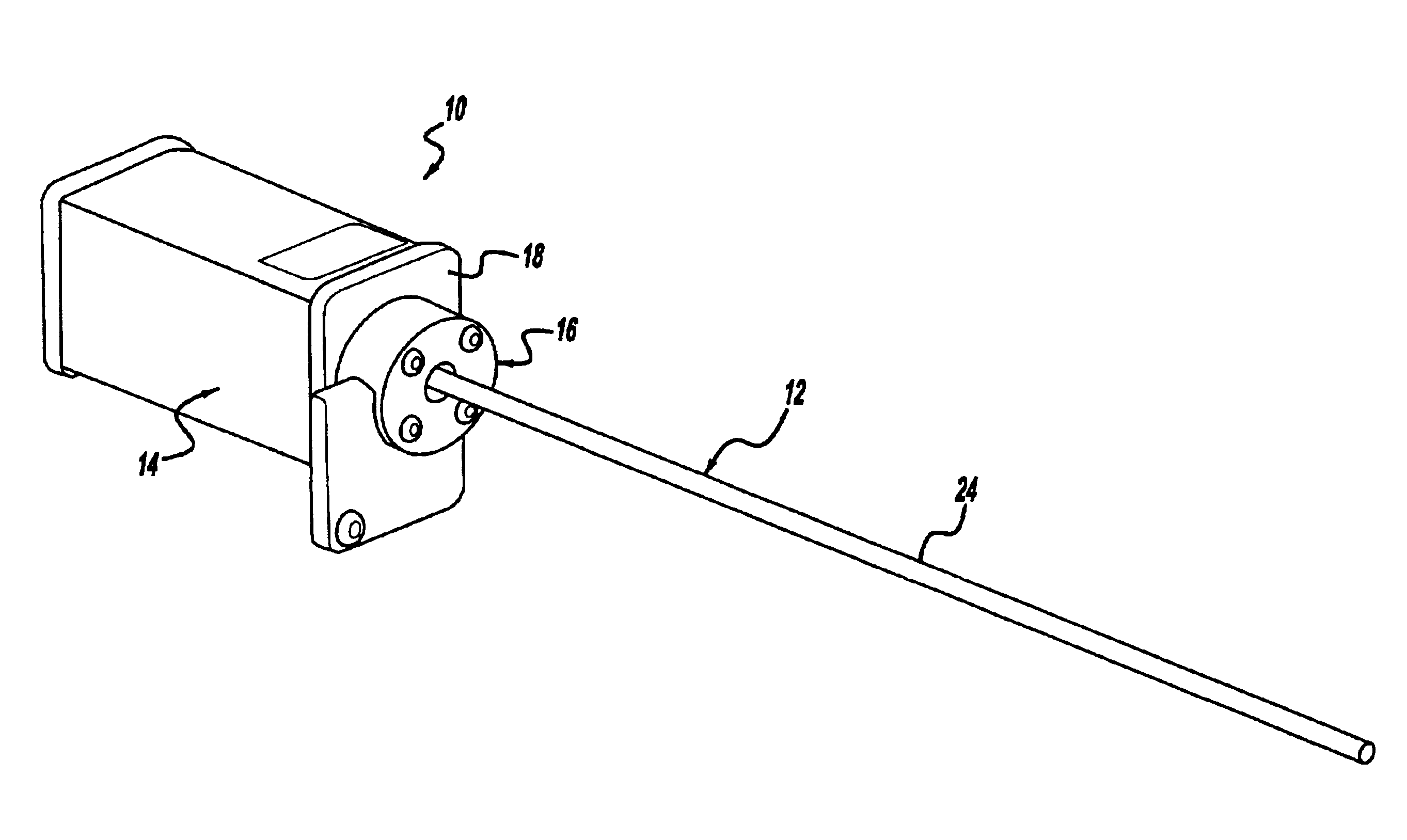
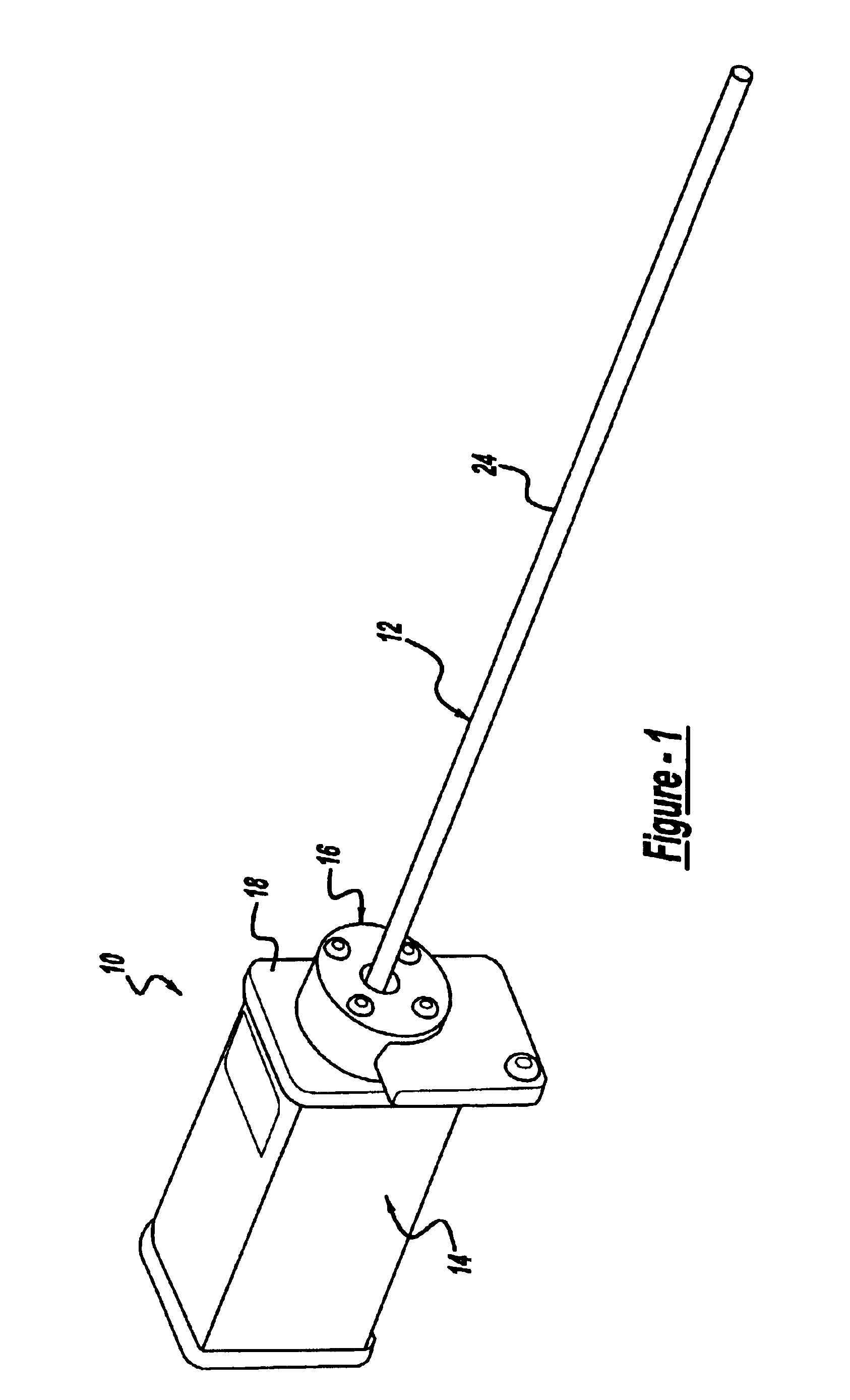
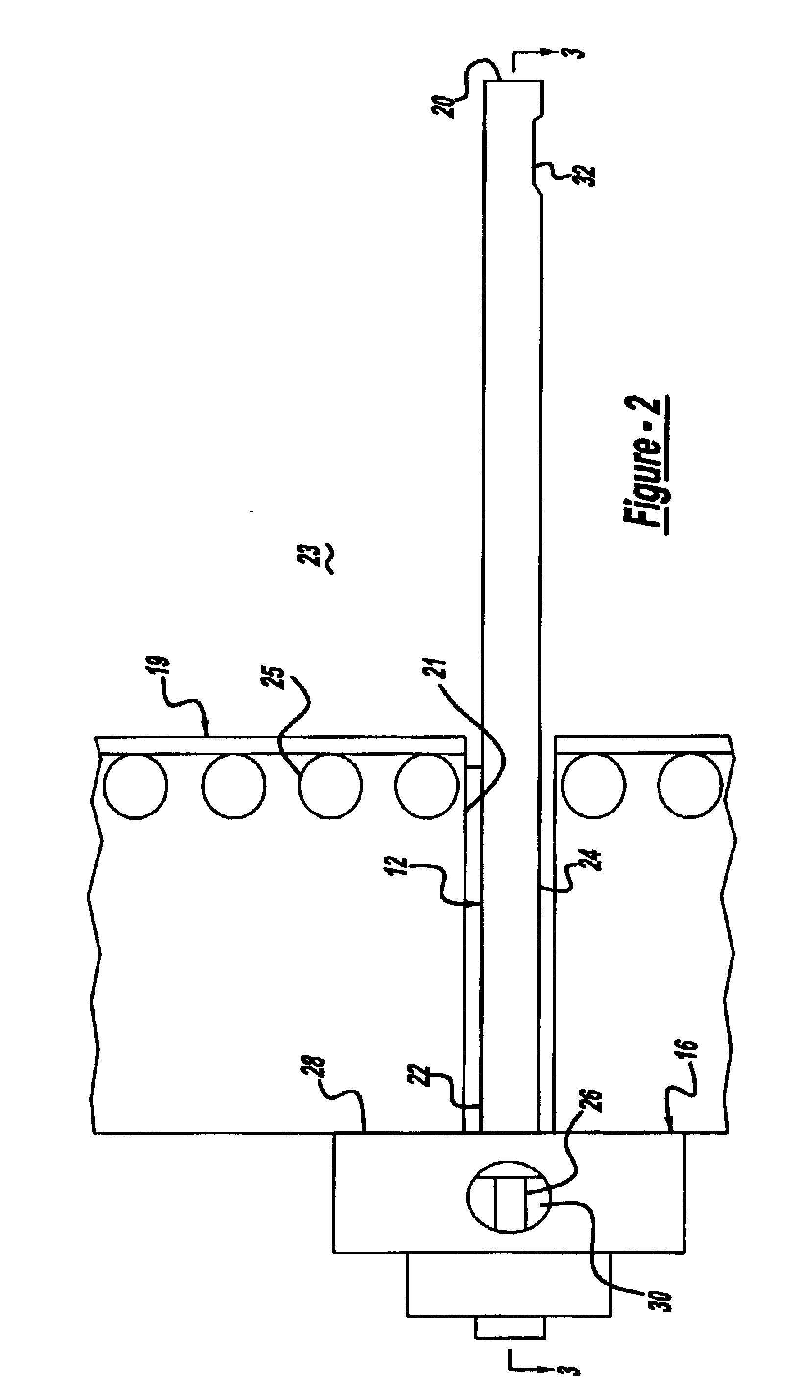
[0032]FIG. 1 illustrates an emissivity probe in accordance with this invention. Emissivity probe 10 principally comprises tube assembly 12 which is attached to sensor housing assembly 14 by flange assembly 16. Bulkhead 18 is provided for mounting the device to an associated boiler inner wall 19 through a port 21(shown in FIG. 2) which enables tube assembly 12 to project into the interior 23 of the boiler, while sensor housing assembly 14 is external to the interior of the boiler and thus protected from the severe environment of the boiler interior. The steam tubes 25 are shown as part of inner wall 19. To facilitate installation, port 21 is preferably lined with port tube 26, which is attached at one end to outer wall 27 and at the other end to inner wall 19.

[0033]FIG. 2 shows tube assembly 12 apart from sensor housing assembly 14. Tube assembly 12 defines distal end 20 and proximal end 22 which is supported by flange assembly 16. Further references in this description to “proximal ...

second embodiment

[0045]Now with reference to FIG. 9, an emissivity probe in accordance with this invention is shown which is generally designated by reference number 60. Emissivity probe 60 features a tube assembly 62 which differs from that previously described. In this instance, outer tube 64 and inner tube 66 do not feature the windows for “side looking” by a reflected optical guide. Rather, each of the guides 68 and 70 have bent ends 72 and 74 for receiving radiation in different directions. Emissivity probe 60 could be used in installations where one of the guide ends 72 or 74 can be directed to an adjacent wall surface, whereas the other guide end is oriented toward the boiler fireball.

[0046]Emissivity probe 60 also differs from probe 10 in that the proximal ends of guides 68 and 70 are bent to diverge. Photodiode adapters 76 and 78 are provided for the same function as previously described. Filters such as filters 51 and 53 shown in FIG. 4 may also be provided. For this embodiment of emissivi...


PUM


Abstract

An emissivity probe for measuring reflected energy from interior wall surfaces of large scale boilers. The emissivity probe uses a pair of light guides which respectively receive light energy from the interior of the boiler and that reflected off a wall surface. Using appropriate photo detectors sensitive to a desired light wavelength range, a ratio of the reflected and incident radiation is provided. This provides a measure of the reflectivity of the wall surface. The reflectivity values are used to control boiler cleaning systems.

Description

FIELD OF THE INVENTION[0001]This invention relates to an emissivity probe of a type adapted for evaluating, through optical inputs, the condition of internal surfaces of large scale combustion devices such as utility and processing boilers.BACKGROUND OF THE INVENTION[0002]In the operation of large scale combustion devices such as coal burning boilers, there is a continual build up of slag deposits on their internal walls and heat transfer surfaces. As the slag builds up on these surfaces, the slag layer reflects some of the radiant heat energy produced within the boiler by combustion and thus, less steam and thermal output is produced by the boiler. Accordingly, it is important to periodically remove the slag layers to maintain efficient operation.[0003]Various means for detecting the presence of slag development on internal surfaces of combustion devices have been developed. One approach is through the monitoring of various operating parameters of the boiler which provide an indire...

Claims


Application Information

Patent Timeline
IPC IPC(8): F22B37/56F22B37/00G01J5/04G01N21/84G01J1/16G01N21/90
CPCF22B37/56G01J5/0003G01J5/0044G01N21/8422G01J5/08G01J5/0821G01J5/0893G01J5/041
Inventor HUSTON, JOHN T.YOUSSEF, SIMON F.
Owner DIAMOND POWER INT
Why Eureka
Try Eureka