[0008]The object of the invention is to develop, for microwelding technology, a welding head which permits monitoring of the ease of motion of the guide shaft, of the readjusting spring, of the functioning of the infeed cylinder, of the clamping of the electrodes, and thus of the welding operation with simple means and also permits the use of this monitoring at welding guns fitted with a welding head.
[0010]By the use of the force measurement between the cylinder and the readjusting spring, the quality of each weld is controlled by monitoring the pressure profile and / or the
maximum pressure during resistance welding with microwelding technology. In this way, high
scrap rates due to faults which have remained unnoticed, for example, during a pure displacement measurement, such as, for example, too slow readjustment of the readjusting spring or inadequate clamping of the electrode fastened thereto, are prevented. Thus the yield of a welding
machine equipped with such a welding head is considerably improved. Due to the often different material properties of the components to be welded, considerable importance is attached to ensuring a continuous welding force at the electrodes. The rapid readjustment of the electrodes during the introduction of the welding current depends on the ease of motion of the guide shaft, on the functioning of the readjusting spring, on the functioning of the infeed cylinder and on the reliable clamping of the electrodes. 100% monitoring of all the functions of the welding head is possible by means of the centrally arranged
pressure sensor. Thus, continuity of the quality of the welds is ensured and at the same time
documentation of each weld for the
quality control is possible via the “good”
signal of the force measurement. In other words, the force or
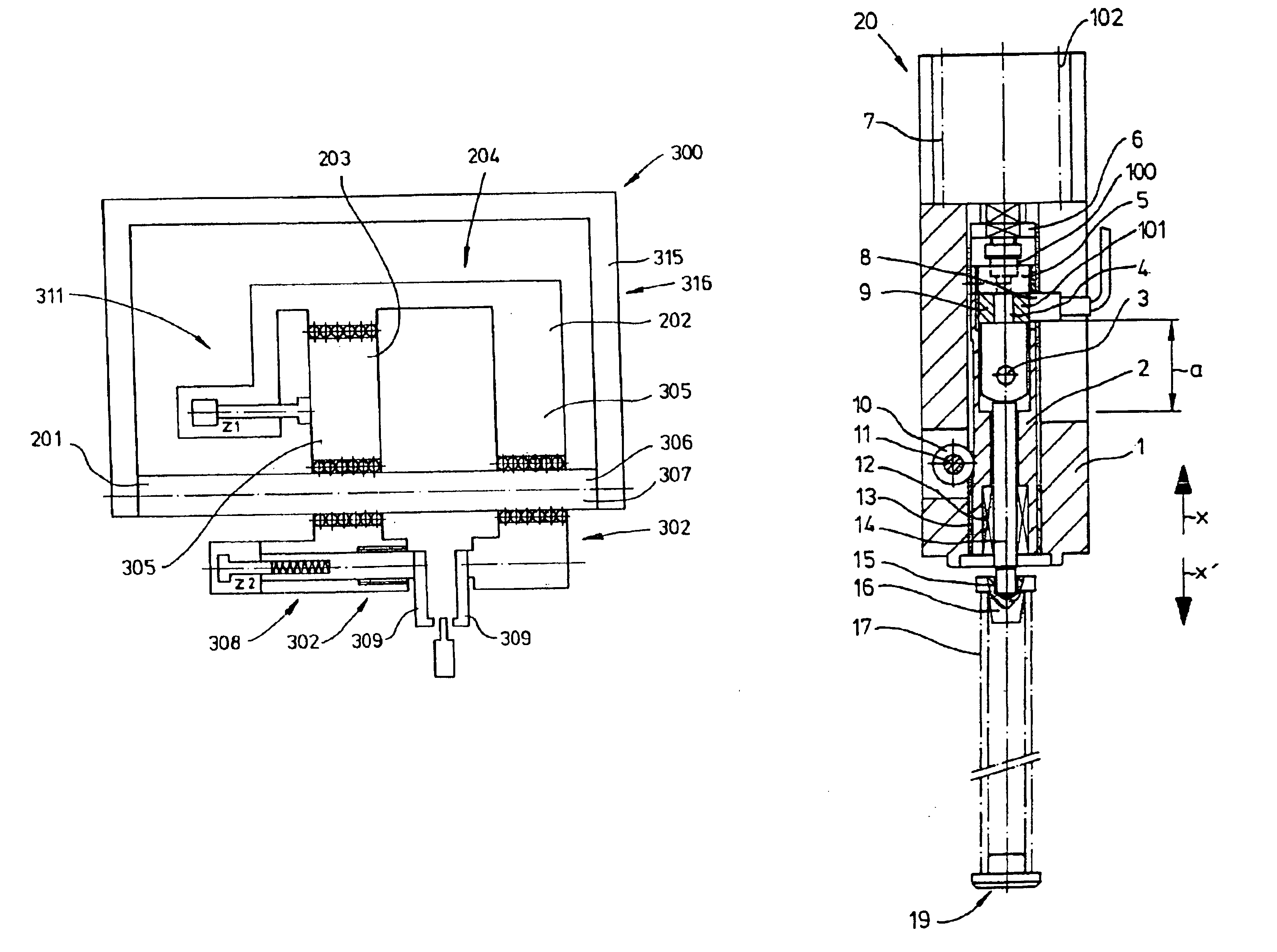
pressure measurement is effected between a pressure-exerting and a pressure-transmitting component. The expression “a pressure-exerting component” refers, for example, to the cylinder or its
piston. The pressure-transmitting components include, for example, the readjusting spring. By such interposition of the
pressure sensor, it is possible to monitor the pressure-exerting components and the pressure-transmitting components, since both are connected to the
pressure sensor and act on the latter. The pressure-transmitting components act on the sensor virtually with a counterpressure, which originates from the electrode resting on the workpiece. The sensor is therefore clamped in place between the pressure-exerting and the pressure-transmitting components.
[0011]Furthermore, the effect of loads originating from the electrode on the sensor is damped by the interposition of the readjusting spring. As a result, the sensor is protected. Monitoring of cylinder and guide shaft is possible by direct contact of the sensor with these components.
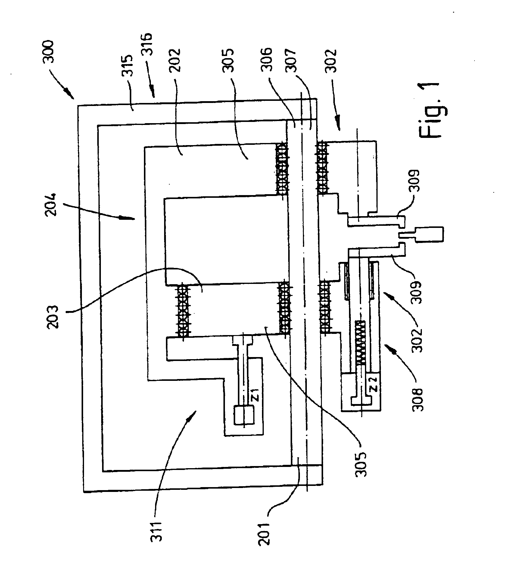
[0015]Due to the arrangement of the welding-gun elements on a common shaft, the welding guns exert identical torques on the shaft. In this way, the shaft is uniformly loaded. By the welding-gun elements being connected to form a C-frame or a bridge, the opposed torques are absorbed in the frame or the bridge to the greatest possible extent and do not cause any canting of the welding-gun elements on the shaft, so that optimum ease of motion of the welding-gun elements on the shaft or guide is ensured.

