High frequency laminated device

Inactive Publication Date: 2005-06-28
PANASONIC CORP
View PDF3 Cites 12 Cited by
  • Summary
  • Abstract
  • Description
  • Claims
  • Application Information

AI Technical Summary

Benefits of technology

[0009]The inductor pattern is short, and the inductor has a large inductance and a

Problems solved by technology

Moreover, thinning of electrode patterns available at present, which have widths of 100 μm, decreases an electrical conductivity of electrode patterns and increases an insertion loss of the LPF.
Further, it is difficult

Method used


Image

  • High frequency laminated device
  • High frequency laminated device
  • High frequency laminated device

Examples


Example

(Exemplary Embodiment 1)

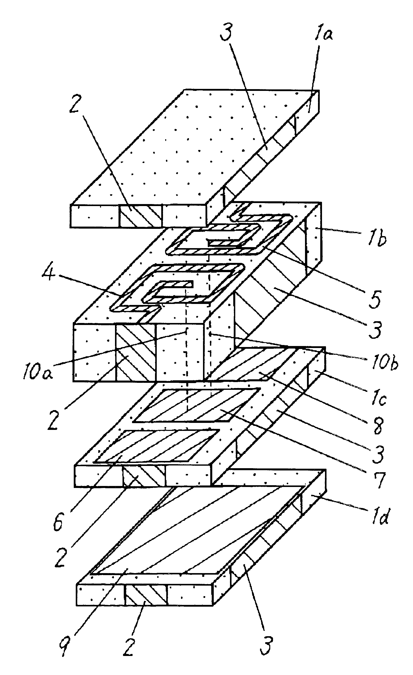
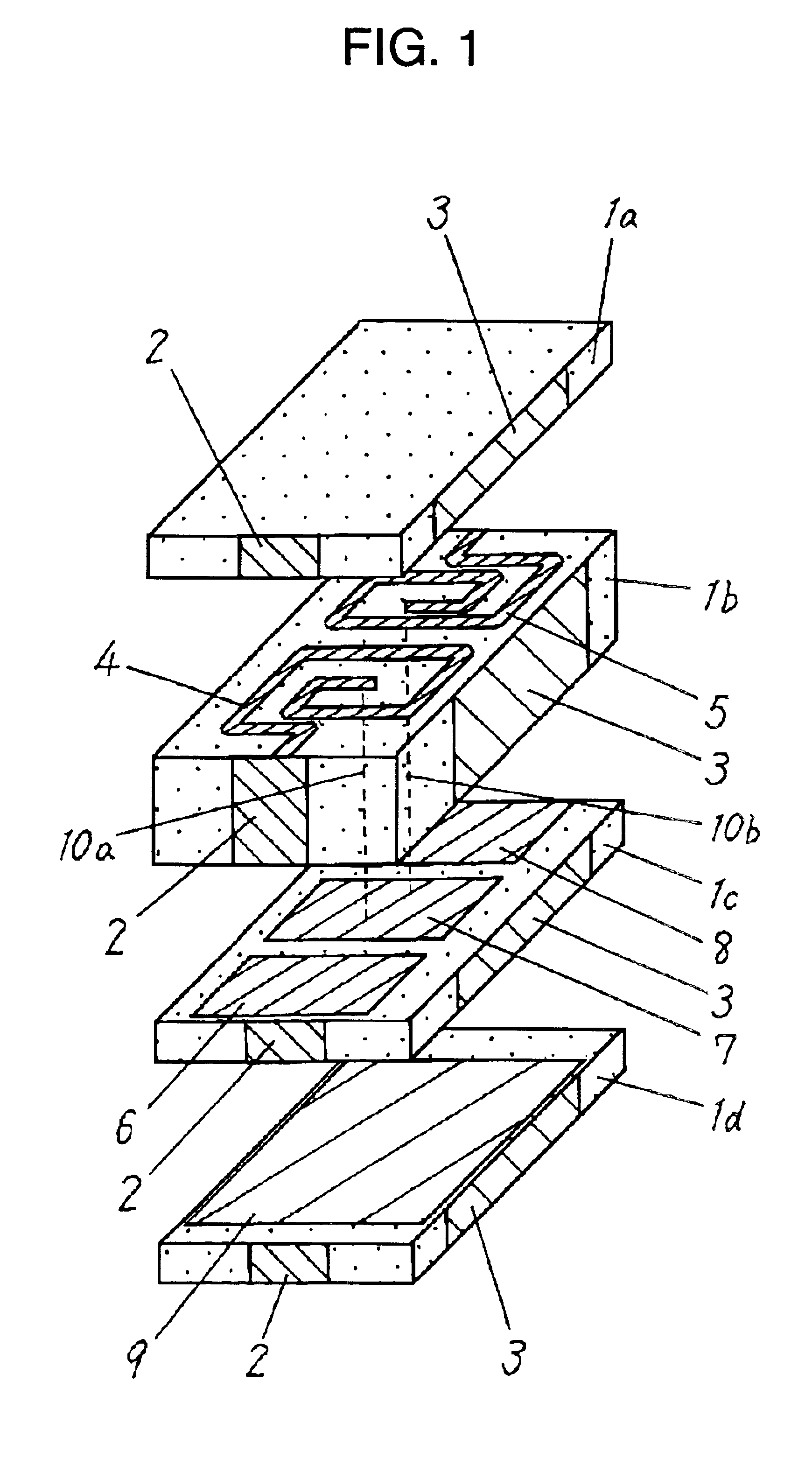
[0024]A laminated low pass filter (LPF) as a high frequency laminated device according to Exemplary Embodiment 1 of the present invention is shown in FIG. 1. The LPF includes magnetic sheets 1a to 1d made of magnetic material having a relative permeability larger than 1, input / output electrodes 2 formed on respective side surfaces of the magnetic sheets 1a to 1d, ground (GND) electrodes 3 formed similarly to the input / output electrodes 2, inductor patterns 4 and 5 for forming an inductor printed on the magnetic sheet 1b, capacitor patterns 6, 7 and 8 for forming capacitors printed on the magnetic sheet 1c, GND pattern 9 printed on the magnetic sheet 1d, and via-conductors 10a and 10b.

[0025]The magnetic sheets 1a to 1d are stacked in an order shown in the figure and are sintered unitarily to provide a laminated body. The ends of the input / output electrodes 2 and inductance patterns 4 are electrically connected to a portion of the capacitor pattern 6, and the ...

Example

(Exemplary Embodiment 2)

[0032]FIG. 6 shows a low pass filter (LPF) as a high frequency laminated device according to Exemplary Embodiment 2 of the invention. The same elements as of an LPF of Embodiment 1 shown in FIG. 1 are denoted by the same reference numerals. The LPF of Embodiment 2, differently from the LPF of Embodiment 1 shown in FIG. 1, includes dielectric sheet 101c instead of magnetic sheet 1c. The other components are basically identical to those of Embodiment 1.

[0033]Capacitor pattern 9 is opposed to capacitor patterns 6, 7, and 8 about the dielectric sheet 101c. This arrangement allows a thickness and a relative dielectric constant of the dielectric sheet 101c to be optimized independently from other sheets, thereby reducing, for example, variations in manufacture of capacitors 6, 7 and 8. That is, a magnetic sheet is used at a portion where an inductor pattern is formed, while the dielectric sheet is used at the portion where the capacitor pattern is formed. This allo...

Example

[0040]As shown in FIG. 9, the antenna duplexer of Embodiment 3 includes a laminated body 11, chip components 12, such as PIN diodes or FET switches, inductors, capacitors, and resistors, and a surface acoustic wave (SAW) filter 13. The laminated body 11 includes magnetic sheets having relative permeabilities larger than 1, and a circuit pattern and a via-conductor formed in the body. As shown in FIG. 10, the device includes an antenna terminal 14, a GSM transmission terminal 15, a GSM reception terminal 16, a DCS transmission terminal 17, a DCS reception terminal 18, a diplexer 19 for separating a GSM signal and a DCS signal, switches 20 and 21, low pass filters (LPFs) 22 and 24, and SAW filters 23 and 25. FIG. 11 shows a circuit including the components in the body. The diplexer 19, a portion of the switches 20 and 21, and LPF 22 and 24 are formed with an LC circuit including inductors and capacitors. Most of the inductors and capacitors are three-dimensionally configured as patter...


PUM


Abstract

A laminated high frequency device includes a laminated body including plural magnetic sheets having relative permeabilities larger than 1, inductor patterns for forming plural inductors in the laminated body, and capacitor patterns forming a capacitor. The capacitor patterns are opposed to each other about another sheet of the laminated body. The inductors have large inductances without thickening of the magnetic sheet or thinning of the inductor patterns providing a large conductor loss. This arrangement reduces a size of the laminated high frequency device while providing isolation between the inductors.

Description

FIELD OF THE INVENTION[0001]The present invention relates to a high frequency laminated device used in mobile communication equipment, such as portable phones.BACKGROUND OF THE INVENTION[0002]Electronic components used in mobile communication equipment, such as portable phones are required to have a small size and a small weight without having their performance decline. A transmission circuit of the mobile communication equipment includes a low pass filter for preventing emission of unnecessary signals, such as higher harmonics. FIG. 12 shows a laminated low pass filter (LPF) as a conventional high frequency laminated device. The LPF includes sheets 101a to 101d, input / output terminal 102, ground (GND) terminal 103, inductors 104 and 105 printed as electrode patterns on the sheet 101b, capacitors 106, 107, and 108 printed as electrode patterns on the sheet 101c, and GND pattern 109 printed as an electrode pattern on the sheet 101d. FIG. 13 shows an equivalent circuit of the LPF.[000...

Claims


Application Information

Patent Timeline
IPC IPC(8): H01F5/00H01G4/228H03H7/075H01F3/10H01F17/00H01F17/04H01G4/30H01G4/40H03H7/01H03H7/46
CPCH01F17/04H01G4/30H03H7/0115H03H7/1758H03H7/1766H03H7/463H01G4/40H01F3/10H01F17/0006H03H2001/0085
Inventor SATOH, YUKIINUZUKA, TSUTOMU
Owner PANASONIC CORP
Why Eureka
Try Eureka