Fan control circuit and package

a technology of fan control circuit and power module, which is applied in the direction of electrical apparatus casing/cabinet/drawer details, electrical apparatus details, and electrical apparatus casings/cabinets/drawers, etc., can solve the problems of large and relatively complex fan control circuits, difficult mounting, troubleshooting or replacing, etc., to eliminate the need for connectors, good heat dissipation, and effective thermal management

Inactive Publication Date: 2005-06-28
ELECTRONICS MOTION SYST HLDG
View PDF10 Cites 17 Cited by
  • Summary
  • Abstract
  • Description
  • Claims
  • Application Information

AI Technical Summary

Benefits of technology

[0008]A power module according to the present invention can provide to each electrical motor a profile of current with fixed or variable frequency and variable duty cycle. This allows for more control over the speed of the motors and thus better control over the cooling rate.
[0014]These conditions provide a power loss that can be dissipated by the power module without compromising its reliability and functionality. A power module according to the present invention can operate at 50 Hz with few modifications to the control circuit.
[0019]In a power module according to the present invention, the flat copper pattern has a wider area than the power switching devices disposed thereon, which results in good heat dissipation due to heat spreading. The heat spreading combined with heat dissipation through the electrical cables allow for effective thermal management.
[0020]Moreover, a power module according to the present invention eliminates connector needs, thereby reducing losses incurred due to connections. In addition, because all of the electrical cables going to and coming from the electrical motors are contained within the power module, the module can be installed and removed more easily. Also, the rubbery enclosure makes the module resilient and thus resistant to vibrations, as well as light weight.

Problems solved by technology

These fan control circuits are large and relatively complex and can be difficult to mount, troubleshoot or replace.

Method used


Image

  • Fan control circuit and package
  • Fan control circuit and package
  • Fan control circuit and package

Examples


Embodiment Construction

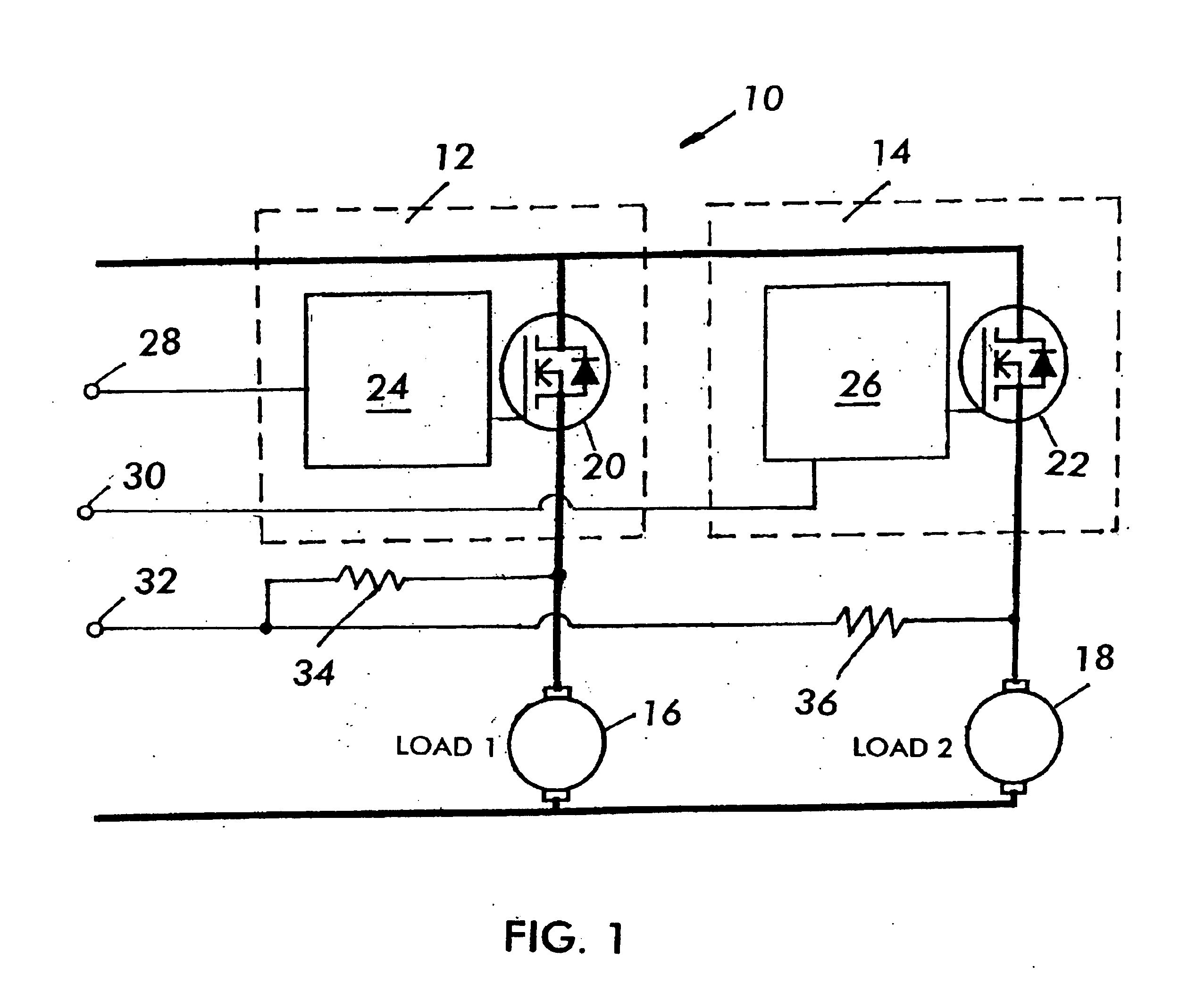
[0033]Referring to FIG. 1, a schematic diagram of a dual output power circuit 10 which may be incorporated in a power module according to the present invention is shown. The dual output power circuit 10 includes two motor driver circuits 12, 14, each for driving a respective motor 16, 18. Each motor driver circuit 12, 14 includes a respective power switching device 20, 22 which is connected between the positive power terminal of a battery +Vbatt and a power terminal of a respective motor 16, 18. Each power switching device 20, 22 is preferably a MOS-gated device such as a power MOSFET, or IGBT. In a preferred embodiment, vertical conduction MOSFETs (GEN7) which are available from the International Rectifier may be used. Other power switching devices, such as power diodes, can also be used in a power module according to the present invention. Each power switching device 20, 22 is switched by a respective control circuit24, 26 according to a desired frequency and for a desired duty cy...


PUM


Abstract

A dual output power module housing a dual output power circuit for providing variable power to two parallel connected fan motors is shown. The power module includes a pad which has disposed thereon two power switching devices, two intelligent power switches, and a power circuit board on which circuits for controlling the intelligent power switches are disposed. The module includes a power shell that surrounds the dual output power circuit, and a resilient, flexible enclosure which encapsulates the power shell and the circuit components within the power shell.

Description

[0001]This application claims priority to U.S. Provisional Application No. 60 / 232,086, filed on Sep. 12, 2000.BACKGROUND OF THE INVENTION[0002]1. Field of the Invention[0003]This application relates to power modules and, more specifically, to a fan control power module for automotive use.[0004]2. Description of the Related Art[0005]Radiators in modern automobiles are typically cooled using two independently controllable fans. The motors that run the fans are controlled using fan control circuits. These fan control circuits are large and relatively complex and can be difficult to mount, troubleshoot or replace.[0006]It is, therefore, desirable to provide a simplified fan control circuit and a module type housing that is small, inexpensive, easy to install and remove, and capable of withstanding the harsh environment in an automobile engine to ensure reliable operation.SUMMARY OF THE INVENTION[0007]In accordance with one aspect of the invention, a dual output power circuit is packaged...

Claims


Application Information

Patent Timeline
Patent Type & Authority Patents(United States)
IPC IPC(8): H05K7/20H05K3/20H05K1/14H05K1/02
CPCH05K7/20209H05K1/0263H05K3/202H05K1/144H01L2224/48137H01L2224/48472H01L2224/4903H01L2224/49111H01L2924/19107
Inventor GRANT, WILLIAM R.FISSORE, SERGIO
Owner ELECTRONICS MOTION SYST HLDG
Why Eureka
Try Eureka