Mass flow sensor and methods of determining mass flow of a fluid

a mass flow sensor and fluid technology, applied in the direction of liquid/fluent solid measurement, instruments, specific gravity measurement, etc., can solve the problems of ineffective or direct coupling of the lowest-order flexural mode, inconvenient measurement of density, and inconvenient measurement of mass flow, so as to extend the system measurement range

Active Publication Date: 2005-07-05
BAKER HUGHES INC
View PDF9 Cites 71 Cited by
  • Summary
  • Abstract
  • Description
  • Claims
  • Application Information

AI Technical Summary

Benefits of technology

[0004]Ultrasonic guided waves that have a principal component of particle displacement in a plane or planes perpendicular to the density-responsive segment of the waveguide, or perpendicular to the direction of wave propagation in that segment, are slowed by a mass loading effect when the density portion of the present invention's waveguide is surrounded by a fluid of density ρ. The effect is generally much greater with liquids compared to gases, and for a given elastic material (stainless steel, titanium, aluminum, for example) the mass loading effect is usually greater for torsion compared with flexural waves, provided the waveguide segment is suitably shaped. Extensional waves propagating along waveguides, i.e., having principal motion parallel to the waveguide axis, exhibit negligible response to mass loading and therefore in most cases are not useful for determining density. On the other hand, this insensitivity to density makes extensional waves well suited for measuring the average temperature within the density segment, facilitating a compact temperature-compensated density and mass flowmeter apparatus. Torsional and flexural waves as used herein preferably propagate in their lowest order mode. By “lowest order mode” is meant one or more of the following: (a) the lowest order mode is actually launched; (b) the lowest order mode is the dominant one received even if higher order modes are launched; (c) the signal shape and / or arrival time, or propagation in the system's elastic waveguide can be adequately explained by neglecting all modes but the lowest order mode. For torsion this guarantees dispersion free propagation in straight waveguide segments of circular cross section such as the lead-in and lead-out portions. For flexural waves, the lowest order mode means at sufficiently low frequency, the wave speed in the waveguide is less than that in the adjacent fluid, avoiding radiation or leakage of energy into that fluid. Conversely, acoustic noise in the fluid, being in the longitudinal mode and generally distributed in the fluid over a wide range of frequencies, arbitrary angles of incidence, and arbitrary phases, does not efficiently or directly couple to the lowest-order flexural mode utilized in the flexural density sensor (nor directly to the lowest-order torsional mode utilized in the torsional density sensor). It is also easier to time echoes of interest if there is only one dominant mode propagating. Equivalently, in a resonance method of sensing, it is easiest to determine the resonant frequency if only one mode is dominant.
[0010]In a further preferred embodiment, the mass flow sensor senses density using a torsional waveguide. Velocity is sensed by transmitting an ultrasonic beam upstream of the waveguide across the flow path for reflection across the flow path downstream of the waveguide to a receiver. By straddling the waveguide with legs of the ultrasonic beam on respective upstream and downstream sides of the waveguide, a modulation of the downstream leg of the beam path occurs as compared with the vortex shedding measurement using the waveguide per se as in the first mentioned embodiment. A contrapropagation measurement over the reflected vee shaped ultrasonic path is thus a check on the accuracy of the velocity measurement using the waveguide and the low frequency detection of vortices shedding from the waveguide. If the waveguide exhibits point symmetry about its long axis, and is centered in line with the vertex of the vee shaped path which straddles it, a symmetrical arrangement is achieved which can measure bidirectional flow, i.e., flow approaching from either of two opposite directions. The contrapropagation method of sensing the vortex shedding frequency provides a cross check on the velocity measurement; moreover, it can extend the system measuring range down to lower Re (pipe Reynolds numbers) than where vortex shedders normally operate (i.e. below Re=10,000) and even down through transitional flow and into laminar flow where Re is less than 2000.
[0011]In a further preferred embodiment of the present invention, the vortex shedding frequency and hence velocity can be determined by the frequency of the change in sign of the circulation of the vortices. Vortices alternate from the top and bottom of the noncircular bluff body of the waveguide. By using two ultrasonic beams downstream of the waveguide each with a transmitter and a receiver and with the beams spaced axially from one another in the direction of flow, the timed differences between, in effect, clockwise and counterclockwise advancements or retardations of the beams passing through the shed vortices can be determined. For example, if the fluid passing between the beams contains a shed vortex having a clockwise circulation (rotation) and the beams are alternated clockwise and counterclockwise faster than the passage of that vortex, the transit time for the clockwise interrogation sense can be compared to the transit time for the counterclockwise interrogation sense. That is, there is a measurable difference in the transit times of the alternating clockwise and counterclockwise beam patterns. Thus, by measuring the difference in transit times around a shed vortex in the fluid of both counterclockwise and clockwise beams while a particular vortex is enclosed between the beams, the transit time in one direction will be faster than the transit time in the opposite direction. By assigning positive or negative values to this circulation, the vortex shedding frequency is detected as a change in sign from positive to negative and vice versa. The frequency of this change in sign is proportional to velocity. Because the change in sign is independent of the shape of the waveguide, provided the shape reliably sheds vortices over a reasonable range of Re (e.g. 10,000 to 100,000), one waveguide segment can be optimally shaped to provide a measurement that is accurate and responsive to density and without undue compromise to its shape to obtain the velocity measurement. The result in this preferred embodiment is an accurate measurement of both density and velocity using the same waveguide segment to provide the density and flow velocity information.

Problems solved by technology

Extensional waves propagating along waveguides, i.e., having principal motion parallel to the waveguide axis, exhibit negligible response to mass loading and therefore in most cases are not useful for determining density.
Conversely, acoustic noise in the fluid, being in the longitudinal mode and generally distributed in the fluid over a wide range of frequencies, arbitrary angles of incidence, and arbitrary phases, does not efficiently or directly couple to the lowest-order flexural mode utilized in the flexural density sensor (nor directly to the lowest-order torsional mode utilized in the torsional density sensor).

Method used


Image

  • Mass flow sensor and methods of determining mass flow of a fluid
  • Mass flow sensor and methods of determining mass flow of a fluid
  • Mass flow sensor and methods of determining mass flow of a fluid

Examples


Embodiment Construction

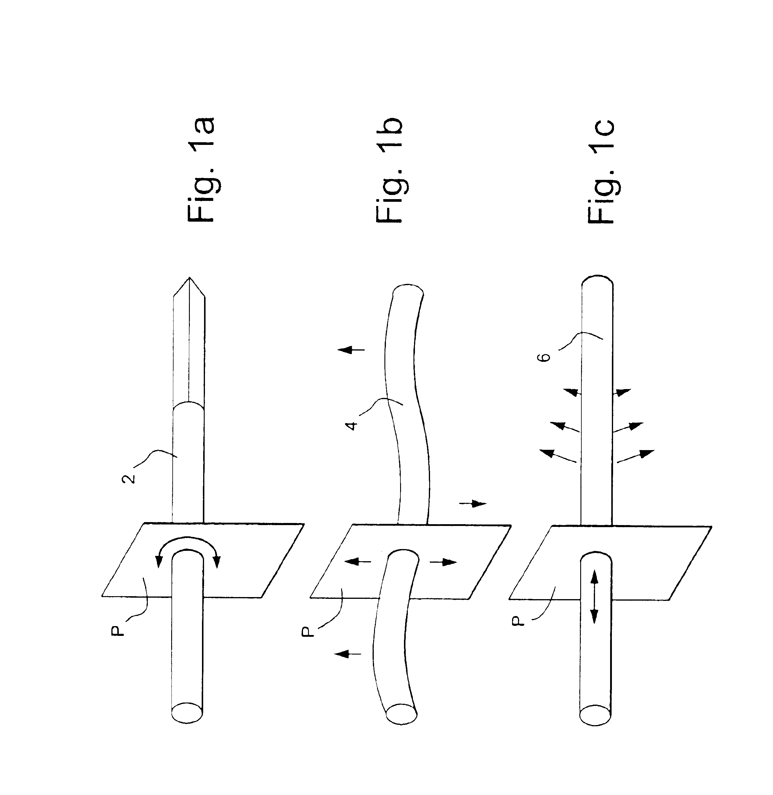
[0035]In FIG. 1a there is illustrated a waveguide 2 which may be excitable in a torsional mode. As illustrated, the principal motion in the waveguide is a vibratory torsional motion in a plane P perpendicular to the long axis of the waveguide. As the torsional wave in waveguide 2 passes the plane P, if it is a lowest order torsional wave, all elements in waveguide 2 that are in that plane rotate either clockwise or counterclockwise about the axis of the waveguide, much like solid body rotation, but on a microscopic scale. In FIG. 1a, a diamond shaped segment of the waveguide noted in the following description is illustrated. Torsional waves propagating along the noncircular diamond portion of the waveguide of FIG. 1a are slowed by a mass loading effect when immersed in a fluid at rest or flowing. The flow may be directed, for example, in a direction perpendicular to the long axis of the waveguide. In FIG. 1b, there is illustrated a waveguide 4 in which the lowest order flexural wave...


PUM

PropertyMeasurementUnit
frequencyaaaaaaaaaa
frequencyaaaaaaaaaa
frequencyaaaaaaaaaa

Abstract

The mass flow rate sensor includes a waveguide disposed in a flow passage having a bluff body facing in an upstream direction. Waves are pulsed along the waveguide for interaction with the fluid. A receiver is coupled to the waveguide to detect a propagated wave and provides a first output signal proportional to the transit time of the propagated wave for determining fluid density. The receiver also provides a second output signal proportional to the shedding frequency of vortices from the waveguide to determine velocity. An electronics module calculates mass flow rate from the velocity times density times area of the flow passage and a constant. In other forms, the velocity is ascertained by transmitting an ultrasonic beam through the shedding vortices to determine vortex frequency which is proportional to velocity.

Description

BACKGROUND OF THE INVENTION[0001]The present invention relates to apparatus and methods for sensing mass flow of a fluid along a flow path and particularly relates to a mass flow sensor using a bluff body in the flow path to determine fluid density and velocity and thereby the mass flow rate in a given flow passage.[0002]In industrial process control, it is often necessary to determine the mass flow rate of fluids along flow paths, e.g. pipes. There are a number of known sensors which provide mass flow rate. For example, one sensor is based on the coriolis principle. Coriolis mass flow meters are generally considered to be highly accurate. However they do have limitations. One such limitation is that they may cause excessive pressure drop in the fluid flow, when sized smaller than adjacent piping to speed up a flow that would otherwise be too low to be readily measured. Other limitations include substantial expense for large sizes of Coriolis flow meters as well as inaccurate or err...

Claims


Application Information

Patent Timeline
Patent Type & Authority Patents(United States)
IPC IPC(8): G01F1/32G01N9/00
CPCG01F1/3218G01F1/3281G01N9/002G01F1/3282
Inventor LYNNWORTH, LAWRENCE C.SMART, CHRISTOPHERNICHOLSON, THOMAS
Owner BAKER HUGHES INC
Why Eureka
Try Eureka