Graphite nanocatalysts

Inactive Publication Date: 2005-07-05
CATALYTIC MATERIALS
View PDF11 Cites 29 Cited by
  • Summary
  • Abstract
  • Description
  • Claims
  • Application Information

AI Technical Summary

Problems solved by technology

While it has been known for many years that both macro and nano-size carbon particles are suitable support materials for certain types of catalysts, it has not been known that some types of graphitic nanostructures, having unique and unexpected properties, are suitable as catalyst themselves, without the addition of a catalytically active metal.

Method used


Image

  • Graphite nanocatalysts
  • Graphite nanocatalysts
  • Graphite nanocatalysts

Examples


examples

Materials

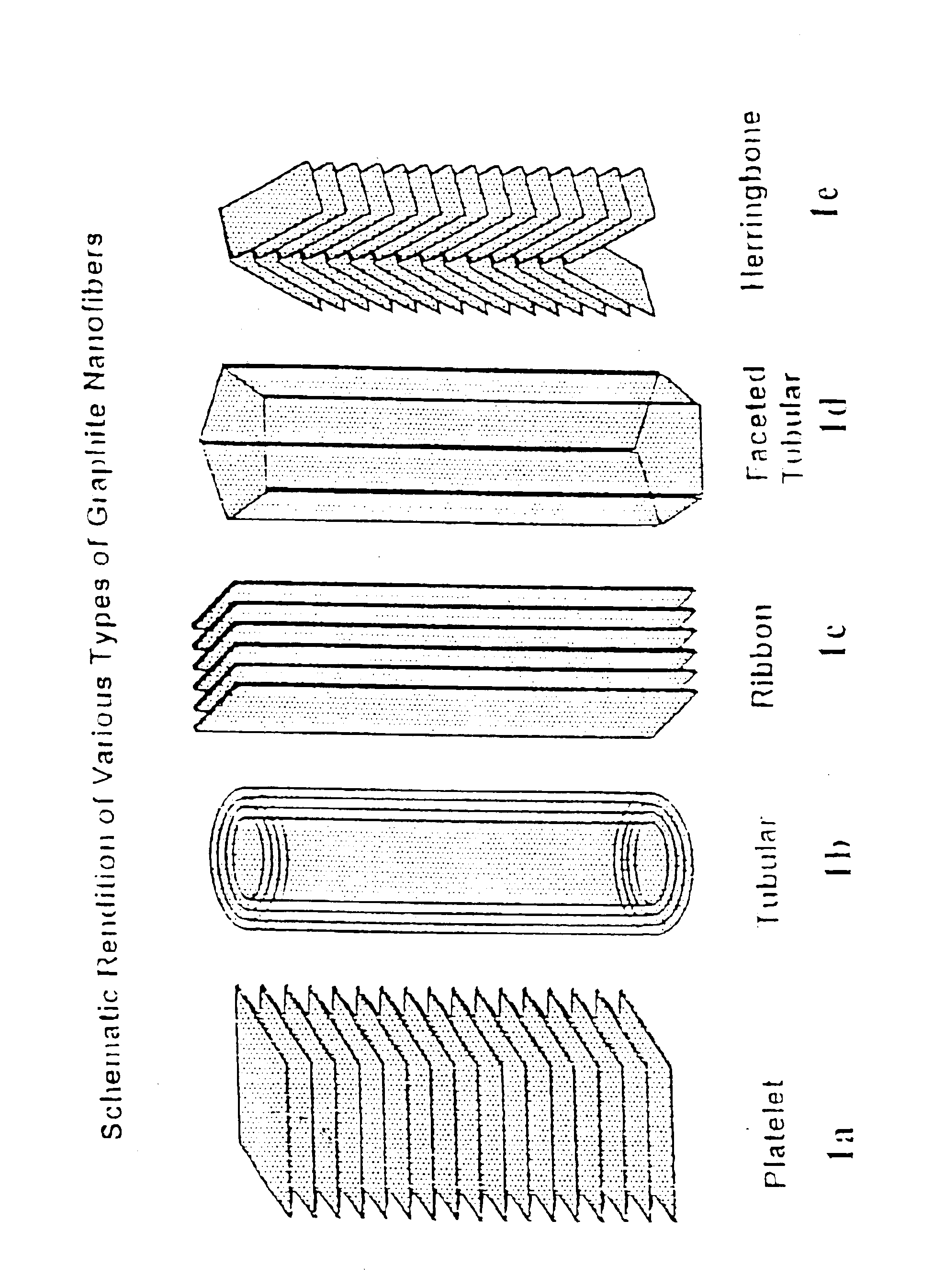
[0041]The “platelet” graphitic nanofibers (CNF-P) used in these examples were prepared from the decomposition of carbon monoxide / hydrogen mixtures over copper-iron powdered catalysts at 600° C. The “faceted tubular” graphitic nanofibers (GNF-T) were grown from the interaction of Co / MgO with carbon monoxide / hydrogen mixtures at 600° C. The “herring-bone” graphitic nanofibers (GNF-H) were produced from the decomposition of ethylene / hydrogen mixtures over powdered copper-nickel catalysts at 600° C. Prior to use all nanofibers were treated in dilute mineral acid for a period of one week to remove the associated metal catalyst particles. For comparison purposes the behavior of two other types of materials were examined; Vulcan XC-72 carbon from Cabot Corp., Pitch-based carbon fibers from Amoco Performance Products and Darco G-60 active carbon.

[0042]The gases used in these examples were carbon monoxide (99.9%), ethylene (99.95%); hydrogen (99.999%), helium (99.99%) and argon (99....

examples 1

Effect of the CO2 / H2 Ratio on the CO2 to CO Conversion

[0044]In this series of experiments at the completion of the graphitic nanofibers growth step, the C2H4 / H2 (4:1) reactant gas mixture was stopped and the solid carbon product treated at 550° C. in a CO2 / H2 (4:1) mixture for 20 mins and cooled to room temperature. Samples were subsequently reacted in various CO2 / H2 mixtures at 400° C. for periods of up to 22 hours. The percentage conversion of CO2 to CO for the various CO2 / H2 mixtures is presented in Table 1 below. Inspection of these data reveals it is necessary to operate at a CO2 / H2 ratio of 1:2 in order to achieve the highest conversion of CO2 to CO.

[0045]

TABLE 1CO2:H2 (10:20)CO2:H2 (20:20)CO2:H2 (15:30)% CO2% CO2% CO2CO2:H2 (20:40)TimeConver-TimeConver-TimeConver-Time% CO2(hr)sion(hr)sion(hr)sion(hr)Conversion0.7520.00.55.60.515.90.7516.12.019.71.05.73.018.01.7516.78.520.222.020.93.516.3

example 2

Effect of Reaction Temperature on the CO2 to CO Conversion

[0046]In a further set of experiments using a 1.0-gram sample of pretreated graphite nanofibers, the CO2 / H2 ratio was maintained constant at (1:2) and the temperature of the system was sequentially increased from 350 to 475° C. At higher temperatures the gasification of the nanofibers by CO2 starts to occur to form CO and a corresponding loss of the catalyst. The maximum temperature was therefore limited to 475° C. The variation in the percent conversion of CO2 to CO is presented as a function of reaction temperature and time in Table 2 below. From these data it is evident that the optimum catalytic conversion of CO2 to CO is achieved at 475° C. Furthermore, provided that the nanofiber catalyst has been activated by pretreatment in CO2 / H2 (4:1) at 550° C. for a short time then it immediately reaches its optimum catalytic performance at any given reaction condition. This finding indicates that the pretreatment is responsible f...


PUM

PropertyMeasurementUnit
temperatureaaaaaaaaaa
temperaturesaaaaaaaaaa

Abstract

Novel catalysts comprised of graphitic nanostructures. The graphitic nanostructure catalysts are suitable for catalyzing reactions such as oxidation, hydrogenation, oxidative-hydrogenation, and dehydrogenation.

Description

CROSS REFERENCE TO RELATED APPLICATIONS[0001]This application is based on Provisional Application 60 / 426,198, filed Nov. 14, 2002.FIELD OF THE INVENTION[0002]This invention relates to novel catalysts comprised of graphitic nanostructures. The graphitic nanostructure catalysts are suitable for catalyzing reactions such as oxidation, hydrogenation, oxidative-hydrogenation, and dehydrogenation.BACKGROUND OF THE INVENTION[0003]Much work has been done over the years in the field of heterogeneous catalysis. Such catalysts have experienced enormous commercial success in many chemical processes, particularly petroleum and petrochemical process applications. Conventional heterogeneous catalysts are typically comprised of one or more catalytically active metals, particularly Group VIII and Group VI metals on an inorganic support. The inorganic support is typically a metal oxide such as alumina, silica, alumina-silica, titania, magnesia, as well as molecular sieves. Various forms of carbon hav...

Claims


Application Information

Patent Timeline
Patent Type & Authority Patents(United States)
IPC IPC(8): C01B31/00C07C2/64C01B31/18C01B31/04C07C4/00C07C5/333C07C5/00C07C4/06C07C2/00C07D301/00C07D301/10D01F9/12D01C5/00B01D53/86B01J21/18B01J23/745B01J23/75B01J35/02B01J35/10C01B3/16C01B13/02C01B17/78C01B21/02C01B32/40C07D
CPCB01D53/8628B01J21/18B01J21/185B01J23/745B01J23/75B01J35/023B01J35/10B82Y30/00C01B3/16C01B13/0203C01B17/78C01B21/02C01B31/04C01B2203/0283C01B2203/1041Y02C20/10B01J35/1019B01J35/1023Y02P20/52C01B32/20
Inventor POLVEREJAN, MIHAIMAROTTA, CHRISTOPHERBAKER, R. TERRY K.
Owner CATALYTIC MATERIALS
Why Eureka
Try Eureka