Simplified transformer design for a switching power supply

a transformer and switching power supply technology, applied in the field of transformers, can solve the problems of high construction cost and heavy weight of the transformer, and achieve the effect of increasing curren

Inactive Publication Date: 2005-07-05
GALAXY POWER
View PDF3 Cites 82 Cited by
  • Summary
  • Abstract
  • Description
  • Claims
  • Application Information

AI Technical Summary

Benefits of technology

[0017]The windings built into the PC board having the power supply components mounted thereon are chosen to be the windings carrying the higher current. The windings carrying the higher current are then continuous traces in the PC board with traces leading to other components of the power supply. The winding carrying the higher current is often the secondary winding. Accordingly, the secondary windings are chosen to be in the PC board with the other components of the power supply. Currents are higher in the secondary circuits when the transformer is a step down transformer, which is the case when the input voltage level is greater than the output voltage level. For example, in many computer applications, the input voltage is in the 10 Volt range, and output voltages are in 1.0 to 4.0 Volt voltage range, with a different DC to DC converter power supply used to provide power at each desired output voltage.

Problems solved by technology

The weight of the transformer presents a problem which the mechanical mounting must overcome.
Also, construction of the transformer is expensive, as it must first be assembled from a variety of separate parts, and secondly it must be mounted on the PC board.

Method used


Image

  • Simplified transformer design for a switching power supply
  • Simplified transformer design for a switching power supply
  • Simplified transformer design for a switching power supply

Examples


exemplary embodiment 400

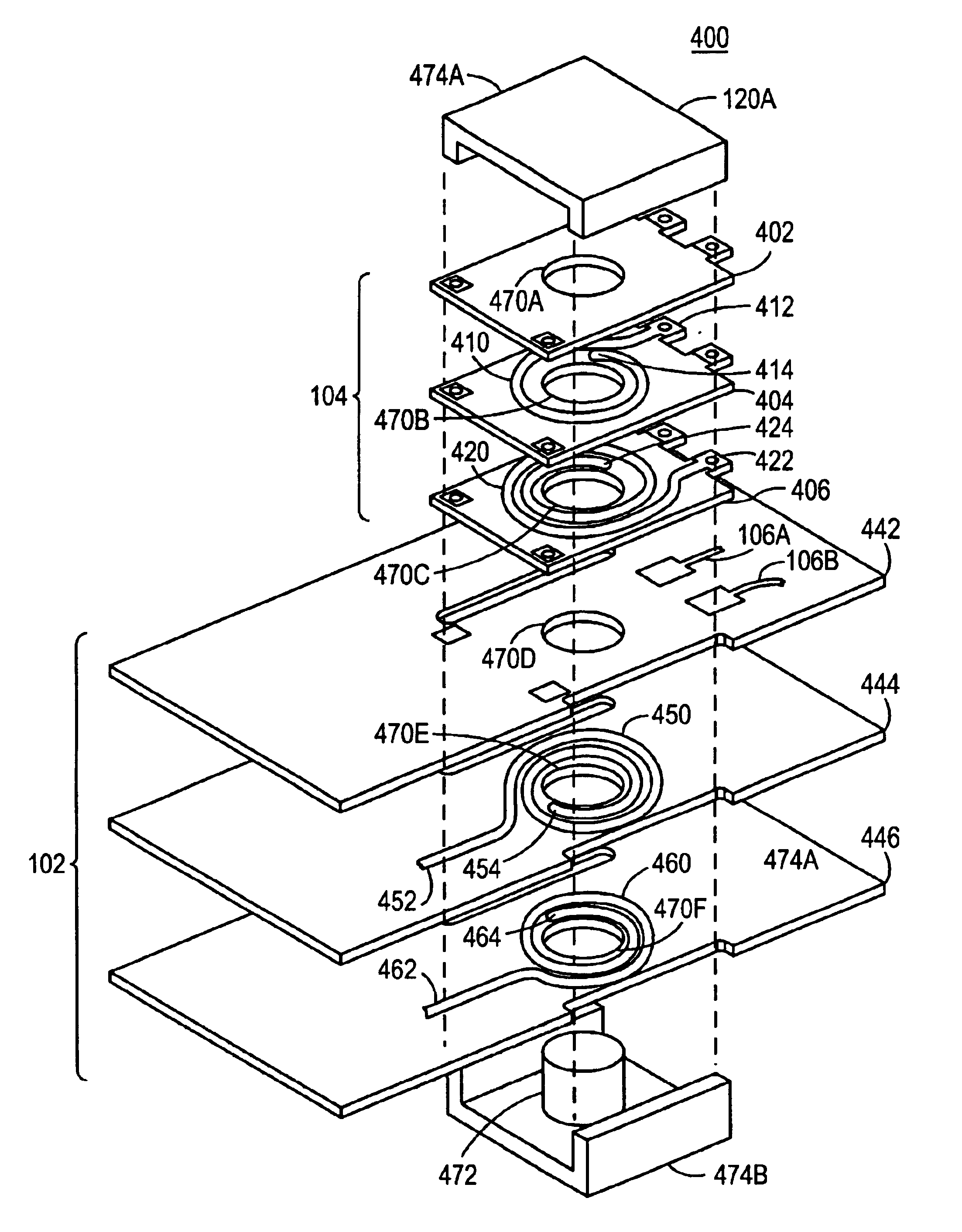
[0045]Turning now to FIG. 4, assembly 400 is shown as an exemplary embodiment of the invention in an exploded view so that the exemplary primary and secondary coils are visible as traces in a multilayer PC board. As shown in exemplary embodiment 400, multilayer small PC board 104 is made up of three PC boards, PC board 402, PC board 404, and PC board 406. Board 402 has a spiral copper trace 410 connected at a first end to electrical connection tab 412, and a second end 414 at the interior of the spiral. Board 406 has a spiral copper trace 420 connected at a first end to electrical connection tab 422, and a second end 424 interior to the spiral. End 414 of spiral trace 410 is “above” end 424 of spiral trace 420. End 414 is electrically joined to end 424 by an electrically conducting via (not shown in FIG. 4) through PC board 404. The electrically conducting via through PC board 404 can be formed by first bonding together PC boards 404, 406 to form a single multilayer PC board. A hole...

exemplary embodiment 500

[0063]As shown in exemplary embodiment 500, a final assembly construction step of bonding an insulating layer 560 to the “bottom” (bottom as drawn) of the assembly is performed. Traces 510 and 504 are left exposed on the “top” surface of the assembly 500. Alternatively, no insulating layer 560 need be bonded to the assembly, leaving trace 534 exposed. As a further alternative, an insulating layer (not shown) could be bonded “above” traces 510504 in order to electrically insulate them from the environment.

[0064]Manufacture of multilayer PC Boards is shown in the book edited by Clyde F. Coombs, Jr. entitled Printed Circuit Handbook, Fourth Edition, published by McGraw Hill, New York, Copyright date 1996, all disclosures of which are incorporated herein by reference, particularly at pages 22.13-22.14, 23.2-23.3, 23.7.

[0065]Turning now to FIG. 6A-FIG. 6E, there is shown construction of a center tapped coil which may be used for either a primary winding or a secondary winding of a transf...


PUM

PropertyMeasurementUnit
electrically conductingaaaaaaaaaa
sizesaaaaaaaaaa
electrical conductingaaaaaaaaaa

Abstract

A transformer has a primary winding made from a first conducting trace formed on a first multilayer printed circuit board, and a secondary winding made from a second conducting trace formed on a second multilayer printed circuit board. The primary winding is magnetically coupled to the secondary winding. The windings are etched as traces in copper layers of the PC boards as spirals. The spiral of one copper layer is connected to the spiral of a different copper layer by a via, or vias, formed through the insulating layer of the PC board. The vias are drilled, cleaned, and plated with conducting material, for example copper. By using multiple layers, and by connecting spiral windings of each layer to the windings of the next layer by use of vias, any number of turns can be built into a primary winding, or into a secondary winding.

Description

BACKGROUND OF THE INVENTION[0001]1. Field of the Invention[0002]This invention relates to the field of electrical transformers, and more particularly to transformers for use on printed circuit boards.[0003]2. Background Information[0004]A transformer ordinarily consists of wire windings around a ferromagnetic core. The windings are usually a primary winding through which electrical current is directed, and secondary windings which are electrically isolated from the primary winding. A magnetic field generated by current flow in the primary winding couples to the secondary winding, and variations in the magnetic field induce current flow in the secondary windings. The ferromagnetic core provides a low reluctance path for the magnetic field.[0005]When used with a printed circuit board (hereinafter PC board), the transformer must be mechanically mounted to the PC board, and must also have its windings electrically coupled to conductive tracings in the PC board.[0006]The weight of the tr...

Claims


Application Information

Patent Timeline
Patent Type & Authority Patents(United States)
IPC IPC(8): H01F27/28H01F27/26H05K1/16H05K1/14
CPCH01F27/266H01F27/2804H05K1/165H01F2027/065H01F2027/2819Y10T29/4902H05K2201/086H05K2201/09063H05K1/141
Inventor FERENCZ, ANDREWZVONAR, GREGORY A.SCHROTER, BERNHARDMILLER, GERALDNG, WILLIAM
Owner GALAXY POWER
Why Eureka
Try Eureka