
Apparatus for flow detection, measurement and control and method for use of same

a flow detection and flow control technology, applied in the direction of instruments, fluid-tightness measurement, liquid/fluent solid measurement, etc., can solve the problems of not working for the same set of piping previously used for both systems, the alarm system used on typical commercial applications will not work for the mps, and the vane-type paddle flow switch is generally not capable of measuring flow with any degree of accuracy. , to achieve the effect of simple operation, easy calibration and higher capacity

Inactive Publication Date: 2005-07-05
YOUNG RICHARD
View PDF11 Cites 51 Cited by
  • Summary
  • Abstract
  • Description
  • Claims
  • Application Information

AI Technical Summary

Benefits of technology

[0050]It is an object of the present invention to provide a fire protection piping system having a water supply, a means for heating water, at least one fire protection sprinkler, a common piping means for receiving water from the supply, passing it through the heating means and delivering it to at least one fire protection sprinkler, and circulating means for circulating water through the common piping back to the heating means to maintain a specified minimum temperature in the common piping. By providing these elements, the danger of water freezing in the common piping is eliminated. In one embodiment, the circulation means comprises a pump controlled by a temperature measurement means for determining when the temperature of water in the piping drops below the minimum temperature specified. The controller engaging the pump which re-circulates the water in the piping through the heating means once the temperature drops below the desired level. At the same time, the recirculating of hot water through the system also eliminates the problem of stagnation.
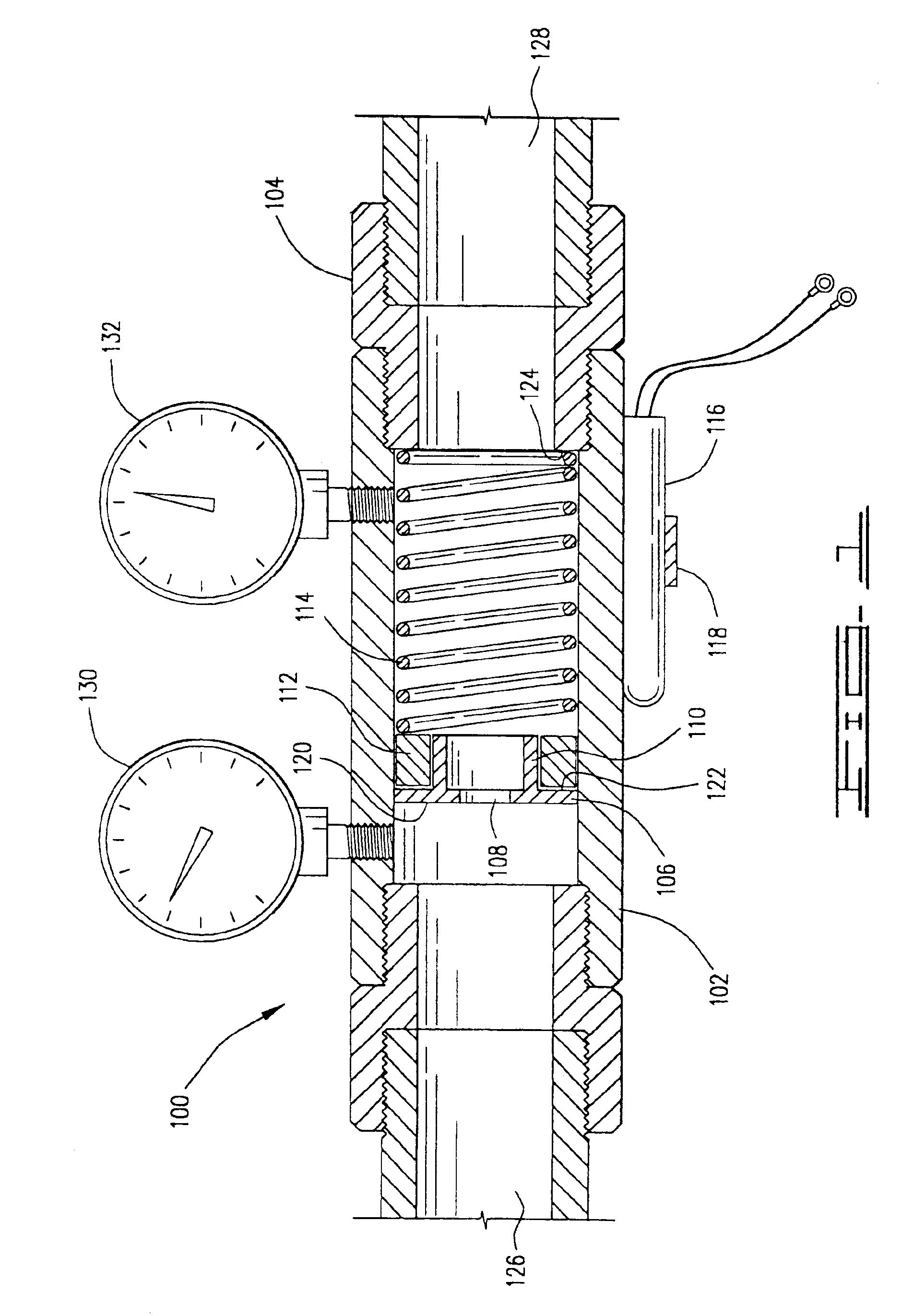
[0054]By the same token, devices previously available for the measurement of flow caused another pressure drop. As noted above, pressure drops in the MPS can prevent sufficient flow from being available to satisfy fire protection needs. Therefore, it is also an object of the present invention to provide a volume flow detection and measurement means for use in the MPS which have minimal pressure drops. The flow detection means discussed are very simple in operation and easy to calibrate in the field. They may be used to provide a read out of the flow, or may simply provide an alarm when fire protection flows are detected.
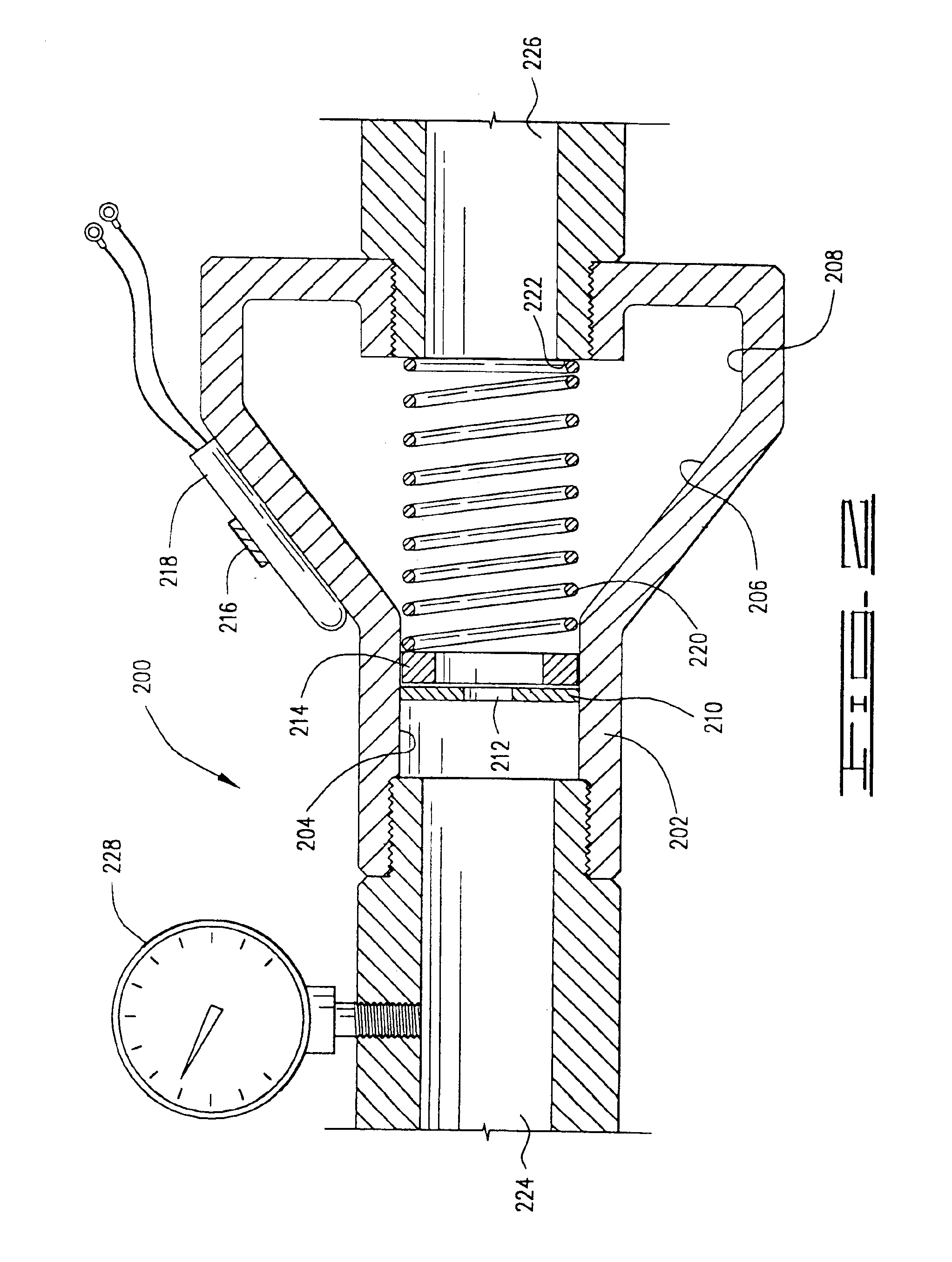
[0055]It is also an object of the present invention to provide a flow measurement device with a higher capacity still for use in standard wet pipe systems. Under some circumstances, it may be desirable to use an expanded chamber system along with the orifice plate. In these devices, as the orifice plate is deflected backwardly by the water pressure and flow, it moves into an area of expanded cross-section where the water can flow not only through the center of the orifice plate, but around the edges thereof This expanded area minimizes the pressure drop through the flow sensor at high demands, such as is the case where multiple sprinkler heads may have activated.

Problems solved by technology

Each type of flow measurement device has its strengths and weaknesses, and may be applicable to one system, while not being suitable for another.
Vane-type paddle flow switches are typically used in the fire protection industry, but vane-type paddle flow switches are generally not capable of measuring flow with any degree of accuracy.
Therefore, the alarm system used on typical commercial applications will not work for the MPS because simply taking a shower might cause a typical commercial flow detector to alarm when used with the MPS.
The same set of piping could not previously be used for both systems because the flow alarm could send false signals when domestic water was turned on.
Therefore, with a smoke detection system and no flow alarm, the fire sprinklers could run for days, causing extensive water damage, while the home owner is away on vacation and no alarm would sound.
Also, smoke detection systems can be expensive.
The problem with Otten and Carmichael is that their devices allow flow therethrough the instant pressure is applied across the orifice plate.
As disclosed, they are not capable of serving as a bypass means for allowing flow only when the differential pressure exceeds some preset level.
Water softeners and similar devices can create substantial drops in system pressure and flow such that the water supply flowing through a typical residential system may not be sufficient for fire protection needs.
Prior art systems also suffered from problems with freezing.
Where lines were in locations that could reach temperatures below freezing, it was a common problem to face freezing in the pipes, which could crack sprinkler heads and / or piping systems.
However, the NFPA provides no means for alarming upon a water flow condition in the MPS, which is a system where both domestic and fire protection systems use common piping.
These non-water-flow-based smoke detection and alarm systems are expensive, and they are not capable of detecting flow through one or more fire protection sprinklers.
The inability of a smoke detection system to detect and enunciate a water flow alarm could result in extensive water damage to the property.
The Tri-Water System allowed for cost savings, but there was one serious flaw; namely, there was no way to provide a water alarm for the sprinkler system.
Thus, the Tri-Water System was a failure.
If paddles are not trimmed for actual flow conditions, nuisance alarms will be sounded; unnecessarily evacuating the building and “rolling” the fire department.
Therefore, this oversight, namely the failure to provide a flow switch, meant that very few Tri-Water Systems were installed, and the concept fell from favor.
In such a case, the flow sensor at the water softener will also measure the cold water flow, potentially contributing to more false alarms in the multi-purpose alarm system.
However, this may be desirable where the risk of false alarms is not substantial, and the cost savings is sufficient enough to justify a single sensor at the water softener only.
It is not believed that the hot water heater will cause a significant pressure drop in the flow therethrough.
However, when an excessive water demand is made on the multi-purpose pipe section, the pressure may drop low enough so that the return leg flow sensor (without an alarm means) allows water to pass there through directly from the first pipe section, bypassing the flow sensor and the other elements of the water heater system.
As noted previously, vane-type switches are very inaccurate in determining flow rate.
Typical domestic flows could have caused an alarm in a prior art system.
These systems without a flow detector risked substantial water damage to the structure if a sprinkler head activated while no one was in the home.
The trouble alarm was created if the domestic usage was excessive.
However, the tamper means is more critical in commercial stand-alone systems.
Both of the elements increased the cost of this system and increased the pressure drop through the system.
In multi-purpose piping systems, as well as stand-alone fire protection systems, there was the problem of stagnation (where water was to be used for human consumption) of water in the piping as well as the problem of freezing, where piping was exposed to temperatures lower than 32° Fahrenheit.
Freezing presented itself as a problem where piping was installed, for example, in an attic of a residence.
Another problem that plagued prior art systems was the issue of retrofitting existing structures for fire protection systems.
Retrofitting for a fire protection system in a typical structure would be very expensive because, where the freezing issue is a problem, piping would have to be installed in conduits below the ceiling of the structure (or at least under insulation) to prevent the danger of freezing.
However, the greater demands of flow required for fire protection purposes had previously prevented this dual use of the piping.
The “tri-water system” which proposed to use the same piping for both purposes provided for a water flow alarm, which made the system undesirable, and eventually resulted in its abandonment.

Method used


Image

  • Apparatus for flow detection, measurement and control and method for use of same
  • Apparatus for flow detection, measurement and control and method for use of same
  • Apparatus for flow detection, measurement and control and method for use of same

Examples


Embodiment Construction

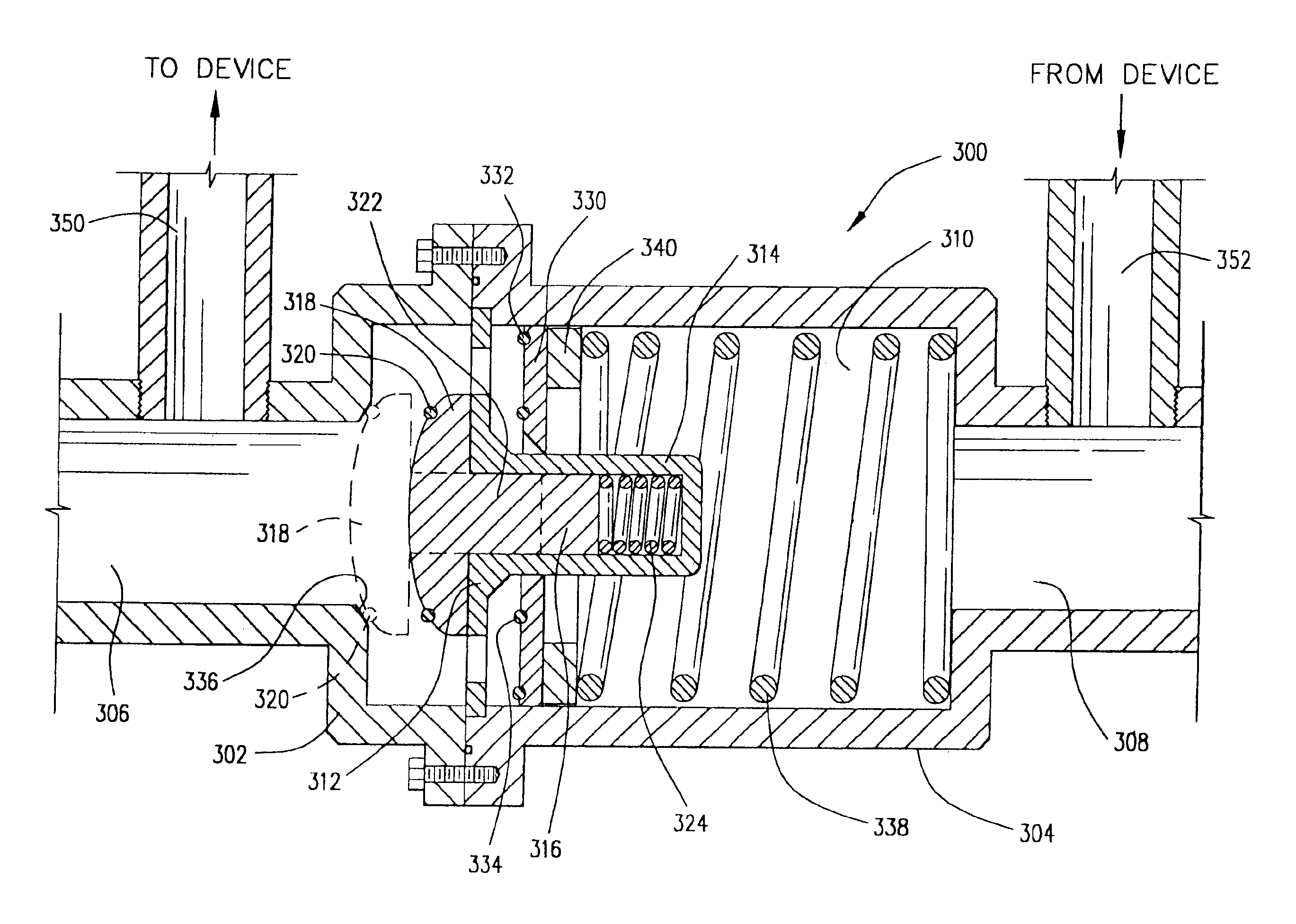
[0094]A flow sensor, from which the flow sensor disclosed herein was described in U. S. patent application Ser. No. 09 / 483,999, filed Jan. 18, 2000. That application disclosed a flow sensor, which could be used with a multi-purpose piping system for a fire suppression system / domestic water supply system in a structure. The device was disclosed as being used in a fire protection system, but it was noted that the sensor could be used in any flow measurement situation as well as in situations where a bypass means was desirable. The device disclosed more fully hereinafter, is intended to, and certainly can, be used in any appropriate flow measurement situation. For example, in a petrochemical facility, materials may be passed through a reactor unit to cause a change in their chemical structure. However, should the reactor become plugged, it may become desirable to have a bypass mechanism which allows the petrochemical to be vented to an emergency flare system, rather than causing a rupt...


PUM


Abstract

A flow sensor having an inlet and an outlet comprising: a plate moving in response to fluid flow therethrough, being displaced further as flow increases; a sensor for determining moving plate's position and creating an electronic signal related thereto; a biasing means for biasing the plate towards the sensor's inlet end. The sensor may include a sealing means for preventing flow therethrough until a specified differential pressure is reached allowing the device to be used as a bypass mechanism. The sealing means may also constitute a check valve means to prevent flow in an undesired direction. The check means comprises: a bullet rod adapted to be received within an orifice defined in a moving plate, such that the bullet rod prevents flow through the orifice until the moving plate is displaced past a terminal end of the bullet rod; and a plate means sealingly and slidingly received within a cylinder, which is closed for a portion of its length and open for another portion of its length, such that flow is prevented until the plate is displaced past the closed portion of the cylinder. The method using the sensor in multipurpose piping systems includes use of the apparatus in a system incorporating at least one fire sprinkler, the piping system also preferably providing at least one other use in the structure. The other use in the structure may be supplying domestic needs, or supplying heating / cooling water for a heating / air conditioning system.

Description

CROSS REFERENCE TO RELATED APPLICATIONS[0001]This application is a continuation-in-part of Ser. No. 09 / 567,510 filed on May 8, 2000, now U.S. Pat. No. 6,333,695, which application was a continuation-in-part of Ser. No. 09 / 483,999 filed Jan. 18, 2000, now U.S. Pat. No. 6,239,708, which was, in turn, a continuation-in-part of Ser. No. 09 / 098,976 filed Jun. 17, 1998, now U.S. Pat. No. 6,081,196 (hereinafter collectively referred to as the “Parent Applications”).BACKGROUND OF THE INVENTION[0002]1. Field of the Invention[0003]The invention relates to the fields of flow detection, measurement and control. The invention also relates to fire suppression systems, and, in particular, to multi-purpose piping systems for fire protection in structures and flow elements related thereto.[0004]2. Description of the Prior Art[0005]Practically any system where fluid flows in a conduit can use flow measurement devices. There are any many different kinds of flow measurement devices as there are systems...

Claims


Application Information

Patent Timeline
IPC IPC(8): G01F1/42G01F1/34G01F1/38G01F1/36G01M3/28G08B21/00G08B21/18G08B17/04
CPCA62C35/68G01F1/26G01F1/28G01F1/363G01F1/38G01F1/42G01M3/2807G01M3/2815G08B17/04G08B21/18F16K37/0041F16K37/005Y10T137/2657
Inventor YOUNG, RICHARD
Owner YOUNG RICHARD
Learn More