Liquid crystal display

a liquid crystal display and active matrix technology, applied in non-linear optics, instruments, optics, etc., can solve the problems of not taking static electricity measurement in the process, reducing the fabrication yield of panels, and reducing the redundancy of the electrostatic protection circuit. , to achieve the effect of reducing the load on the first tft, gentle static electricity, and improving the redundancy of the electrostatic protection circui

Inactive Publication Date: 2005-07-05
SHARP KK
View PDF12 Cites 49 Cited by
  • Summary
  • Abstract
  • Description
  • Claims
  • Application Information

AI Technical Summary

Benefits of technology

[0024]Another object of the present invention is to provide a liquid crystal display provided with a sufficient protection function against static electricity generating relatively low voltage for a long period of time.
[0027]Another object of the present invention is to provide a liquid crystal display having the electrostatic protection element section which is simple in structure of the device and not disadvantageous in an aspect of controlling the current.
[0035]In the conventional electrostatic protection circuit short-circuiting the gate electrodes (G) of the second and the third TFT's 532 and 534 with the bus line 502 and the short ring 506 respectively as shown in FIG. 30, the current does not flow in the second and the third TFT's 532 and 534 in reality and the electrostatic protection circuit is used only for controlling the gate potential of the first TFT 530. On the other hand, the first and the second resistors or the second and the third TFT's of the present invention show a two-way conductivity between the bus line and the short ring, thereby enabling the current to flow. Thus, the first and the second resistors or the second and the third TFT's have a function of preliminarily releasing the charge due to static electricity before the first TFT for primarily running the current sufficiently conducts. In other words, since the current preliminarily flows in the second and the third TFT's, the load on the first TFT can be reduced and the redundancy of the electrostatic protection circuit can be improved.
[0036]Further, the gate electrode of the first TFT of the present invention is connected with the bus line and the short ring via capacitors and the potential of the gate electrode gently varies for a time required to charge and discharge these capacitors. Therefore, according to the structure of the present invention, gentle static electricity can sufficiently be dealt with. When the capacitor is inserted between the gate electrode of the first TFT and a common conductor between the second and the third TFT, a reaction becomes gentle as a whole further and the efficiency as the electrostatic protection element is improved.
[0038]On the contrary, for example, describing this embodiment with reference to FIG. 3, in the structure according to the present invention, if the gate electrode (G) and the source electrode (S) of the second TFT 38 are short-circuited and the gate electrode (G) and the drain electrode (D) of the second TFT 38 are also short-circuited and at the same time the gate electrode (G) and the drain electrode (D) of the first TFT 32 are short-circuited, the function as the electrostatic protection circuit is lost. Similarly, when the gate electrode (G) and the source electrode (S) of the third TFT 40 are short-circuited, and the gate electrode (G) and the drain electrode (D) of the third TFT 40 are also short-circuited and at the same time the gate electrode (G) and the drain electrode (D) of the first TFT 32 are short-circuited, or when the gate electrode (G) and the source electrode (S) of the second TFT 38 are short-circuited, the gate electrode (G) and the drain electrode (D) of the second TFT 38 are also short-circuited, the gate electrode (G) and the drain electrode (D) of the second TFT 38 are also short-circuited, the gate electrode (G) and the source electrode (S) of the third TFT 40 are also short-circuited, and at the same time the gate electrode (G) and the drain electrode (D) of the third TFT 40 are short-circuited, the function as the electrostatic protection circuit is lost. In other words, according to the specific circuit of the present invention shown in FIG. 3, when the elements in the circuit short-circuit at more than three places, then the function stops for the first time as the electrostatic protection circuit. Thus, since the gate in the electrostatic protection circuit according to the present invention is in a floating state, the redundancy for a shortage of the structuring elements is also superior.
[0042]Since the anti-electrostatic element formed according to the present invention is easy to control the resistance (current control) and the structure is simple as well, a stable resistive component can be held. Further, since an arbitrary resistive component can be formed by the method previously described, the array inspection can be possible and a sufficient protective function against static electricity can also be held by constructing the resistive component.

Problems solved by technology

Therefore, if static electricity is generated on the substrate on the array side during a period from the substrate process on the array side constructing the TFT to the panel process sealing liquid crystal by attaching the substrate on the array side and the opposing substrate and a mounting a driver IC and the like, defects such as a destruction of the TFT, a change in characteristics of the TFT, a shortage between each of the bus lines are generated, thereby resulting in a considerable reduction in fabrication yield of panels.
However, according to this method, since each bus line is short-circuited to each other, an independent signal can not be applied to each bus line.
Therefore, a problem occurs, in which an array inspection (a TFT inspection) performing a characteristic test of the TFT of each pixel by detecting the amount of electric charges when the electric charges are kept between the pixel electrode and the common electrode in the display panel can not be performed.
Thus, a problem exists in which a measure against static electricity is not taken in the processes after the unit assembling process.
Thus, a problem that an external size of the panel becomes large exists.
However, since the structure of this electrostatic protection element 500 has a single structuring element, the redundancy is poor.
Further, even if irregularities due to static electricity do not occur, if the electrostatic protection element 500 is short-circuited due to some reason, a TFT test can not be performed.
Thus, when the voltage is relatively low (˜ several volts) due to static electricity, the efficiency of releasing the electric charges is reduced.
Also, based on the previous fabrication experiences, obstacles due to static electricity are known to be occurred by sharp pulse-like static electricity at extremely high voltage for a short period of time and static electricity continuously applied to each element for a long period of time even if the voltage is relatively low.
Further, according to the electrostatic protection circuit described in the above publication, since the current due to static electricity all flows in the first TFT, the redundancy is poor and the load is exceedingly increased, therefore the possibility of the first TFT to be destroyed exists.
Although in the method arranging the high resistive component by the non-linear element such as the two-way transistor, the high resistive component can be formed in a relatively small area, problems occur with respect to controlling the current since the structure of the device becomes complex and moreover the resistive component is altered by an external charges (for example, static electricity) owing to the non-linear element.
Further, since the high resistive component can not be formed outside the ensured area for operation of operating semiconductor film of the transistor such as the area adjacent to an end face of glass, a problem of not being able to make the size of the panel large against a mother glass exists.
Accordingly, although the short ring is required to be removed in the panel process or in the unit assembly process after the panel is completed according to the conventional liquid crystal display, a problem exists in which a measure against static electricity can not be taken in the processes after the short ring is removed.
Further, in the method arranging the zigzag pattern using the ITO, a problem exists in which if the length of the zigzag pattern is long, the external size of the panel becomes large.
Furthermore, the conventional liquid crystal display has problems in which the electrostatic protection element (circuit) for preventing a device destruction due to static electricity is poor in redundancy, the area between the bus line and the short ring is easily short-circuited or the electrostatic protection element does not function as a protection circuit against the static electricity generating m relatively low voltage for a long period of time.
Also, if the non-linear element such as the two-way transistor is used as the high resistive component, the structure of the device becomes complex and the aspect of controlling the current is disadvantageous as well.
Further, since the non-linear element can not be formed adjacent to the end face of the glass, a problem of not being able to make the size of the panel large against the mother glass exists.

Method used


Image

  • Liquid crystal display
  • Liquid crystal display
  • Liquid crystal display

Examples


first embodiment

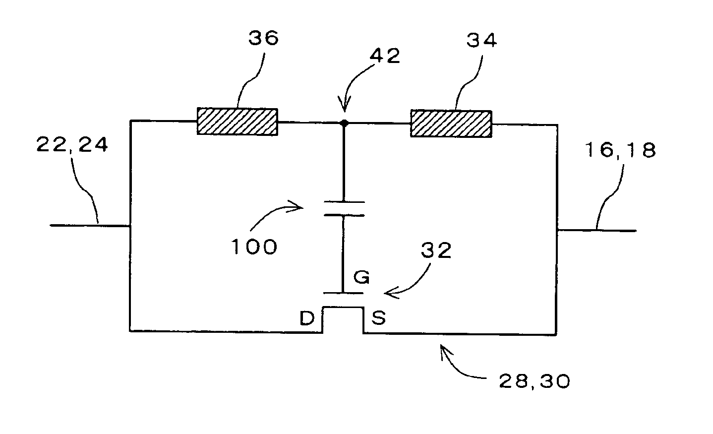
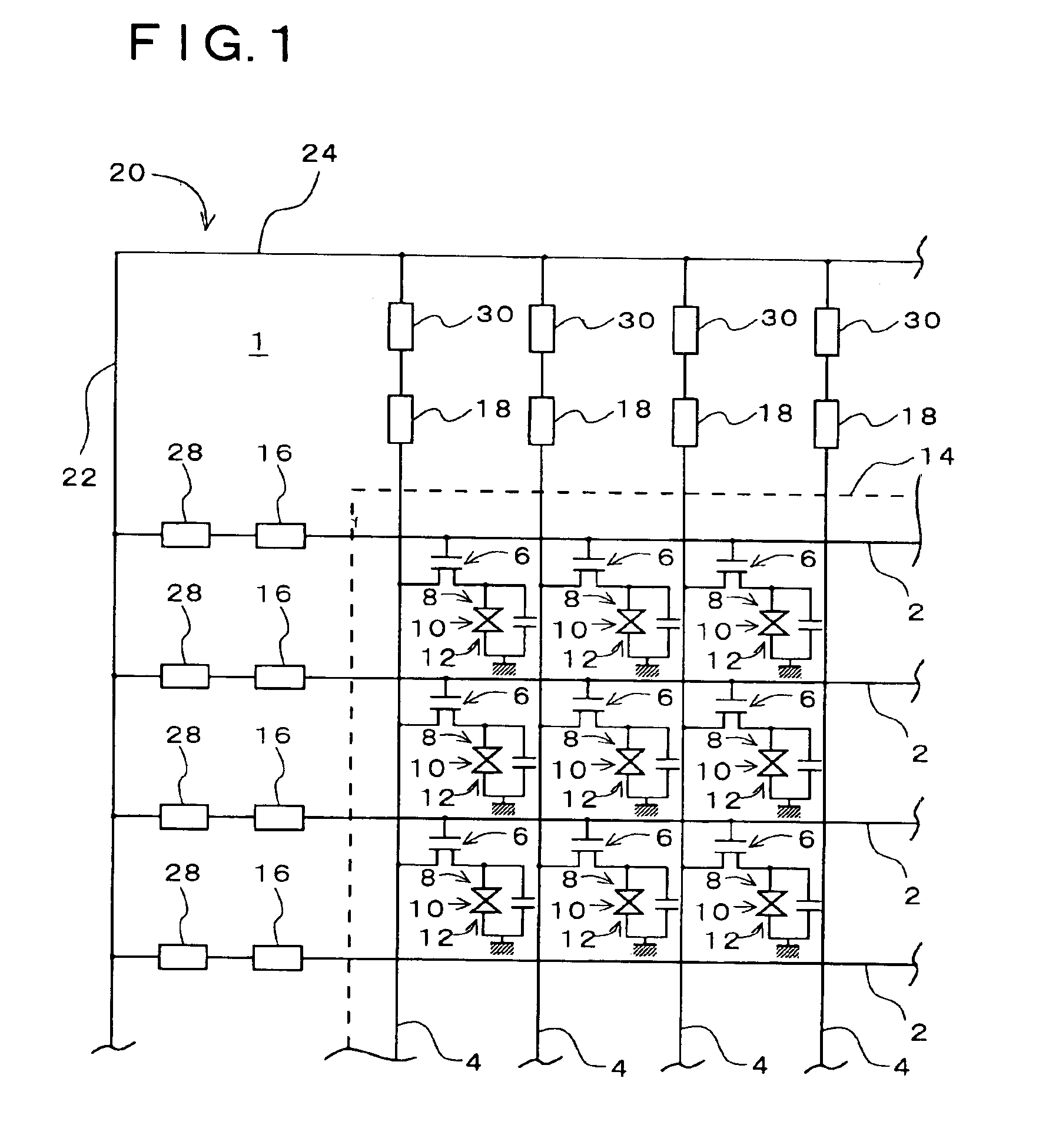
[0074]A liquid crystal display according to the present invention is described with reference to FIG. 1, FIG. 2a and FIG. 2b. First, a schematic structure of the liquid crystal display according to this embodiment is described with reference to FIG. 1. FIG. 1 shows a part of a substrate 1 on an array side of this liquid crystal display viewing toward a substrate surface. It will be noted that inside of a pixel area shows an equivalent circuit for driving liquid crystal. On the substrate 1 on the array side, a plurality of gate bus lines 2 extending in the horizontal direction in the diagram are formed in parallel in the vertical direction. Furthermore, although omitted in the diagram, an insulation film is formed on the plurality of gate bus lines 2, and a plurality of data bus lines 4 are formed on the insulation film in substantially orthogonal to the gate bus lines 2. Each area decided by the gate bus lines 2 and the data bus lines 4 which cross orthogonally to each other in a ma...

second embodiment

[0116]If the common TFT 41 is used in place of the third TFT 40 in the electrostatic protection element sections 28 and 30 of all the bus lines, the number of structuring elements per a bus line can be approximately 2 and the number of elements used in the electrostatic protection circuits can be reduced to approximately half.

[0117]Next, the structure of the electrostatic protection circuit according to this embodiment is described with reference to FIG. 17. FIG. 17 shows a state of a single electrostatic protection circuit on the substrate 1 on the array side when viewing toward the substrate surface. In FIG. 17, the electrostatic protection element sections 28-1 and 28-n are formed between the common wiring 22 extending vertically in the left side on the diagram and the external output electrodes 16-1 and 16-n.

[0118]In this example, the conductor 42 extends vertically in the diagram and is connected to the gate electrodes of a plurality of the first TFT's 32-1 through 32-n. Furth...

eighth embodiment

[0126]Next, a liquid crystal display according to the present invention is described. To begin with, a fabrication process of the substrate on the array side for a TFT-LCD used in this embodiment is briefly described. First, a gate metal is deposited and patterned on the substrate on the array side, and the gate bus line and the gate electrode of the TFT in each pixel area are formed. Second, the gate insulation film is formed on the whole surface and an a-Si layer to be an operating semiconductor film of the TFT and an insulation film for forming a channel protection film are deposited in this order on the gate insulation film. Third, by a back exposure using the bus line and the gate electrode as a mask and an exposure using an ordinary mask to electrically separate the a-Si layer from the pixel area, the above insulation film is patterned and the channel protection film is formed. Fourth, an n+ layer to be an ohmic contact layer, the drain / source electrodes and a drain metal (for...


PUM

PropertyMeasurementUnit
resistanceaaaaaaaaaa
conductiveaaaaaaaaaa
channel lengthaaaaaaaaaa

Abstract

The present invention relates to a liquid crystal display provided with an electrostatic protection element and an object of the present invention is to provide the liquid crystal display provided with superior redundancy and at the same time a sufficient protection function against static electricity in which relatively low voltage generates for a long period of time. Electrostatic protection element sections 28 and 30 are provided with a first TFT 32 having a source electrode (S) and a drain electrode (D) where the source electrode (S) is connected to external output electrodes 16 and 18 and the drain electrode (D) is connected to common wirings 22 and 24, a second TFT 38 having a conductor 42, a source electrode (S), a drain electrode (D) and a gate electrode (G) where the conductor 42 is connected to the gate electrode (G) of the first TFT 32, the source electrode (S) is connected to the external output electrodes 16 and 18, the drain electrode (D) is connected to the conductor 42 and the gate electrode (G) is electrically floated, and a third TFT 40 having a source electrode (S), a drain electrode (D) and a gate electrode (G) where the source electrode (S) is connected to the common wirings 22 and 24, the drain electrode (D) is connected to the conductor 42 and the gate electrode is electrically floated.

Description

BACKGROUND OF THE INVENTION:[0001]1. Field of the Invention[0002]The present invention related to an active matrix type liquid crystal display provided with a thin film transistor (hereinafter, referred to as TFT) as a switching element, and specifically relates to the liquid crystal display provided with an electrostatic protection element protecting the TFT formed on a substrate on an array side and areas between bus lines from a destruction or a shortage due to static electricity.[0003]2. Description of the Related Art[0004]The active matrix type LCD is widely used in computers or equipment for the use of OA (Office Automation) as a flat panel display providing superior picture quality. In this active matrix type LCD, a voltage is applied electrode from both electrodes to a liquid crystal layer sealed between the substrate on the array side forming TFT and pixel electrode and an opposing substrate forming common, thereby driving liquid crystal.[0005]A plurality of gate bus lines ...

Claims


Application Information

Patent Timeline
Patent Type & Authority Patents(United States)
IPC IPC(8): G02F1/13G02F1/1362G02F1/136
CPCG02F1/136204G02F1/136
Inventor NAGASE, YOJITANAKA, YOSHINORIFUJIKAWA, TETSUYANASU, YASUHIRO
Owner SHARP KK
Why Eureka
Try Eureka