Microstructured optical fiber and optical module

a technology of optical fibers and microstructures, applied in the field of microstructured optical fibers, can solve the problem that the sub medium is not necessarily able to constitute an optical fiber by itself, and achieve the effect of reducing the effect of optical fibers, facilitating closure, and small effective area

Active Publication Date: 2005-07-05
SUMITOMO ELECTRIC IND LTD
View PDF12 Cites 20 Cited by
  • Summary
  • Abstract
  • Description
  • Claims
  • Application Information

AI Technical Summary

Benefits of technology

[0007]The present invention fulfills the above described fiber characteristic needs, while overcoming the drawbacks of the prior art, at least in part, by provision of fiber in which chromatic dispersion is flat over a broad wavelength range with a small effective ar

Problems solved by technology

On the other hand, a sub medium is not necessari

Method used


Image

  • Microstructured optical fiber and optical module
  • Microstructured optical fiber and optical module
  • Microstructured optical fiber and optical module

Examples


Embodiment Construction

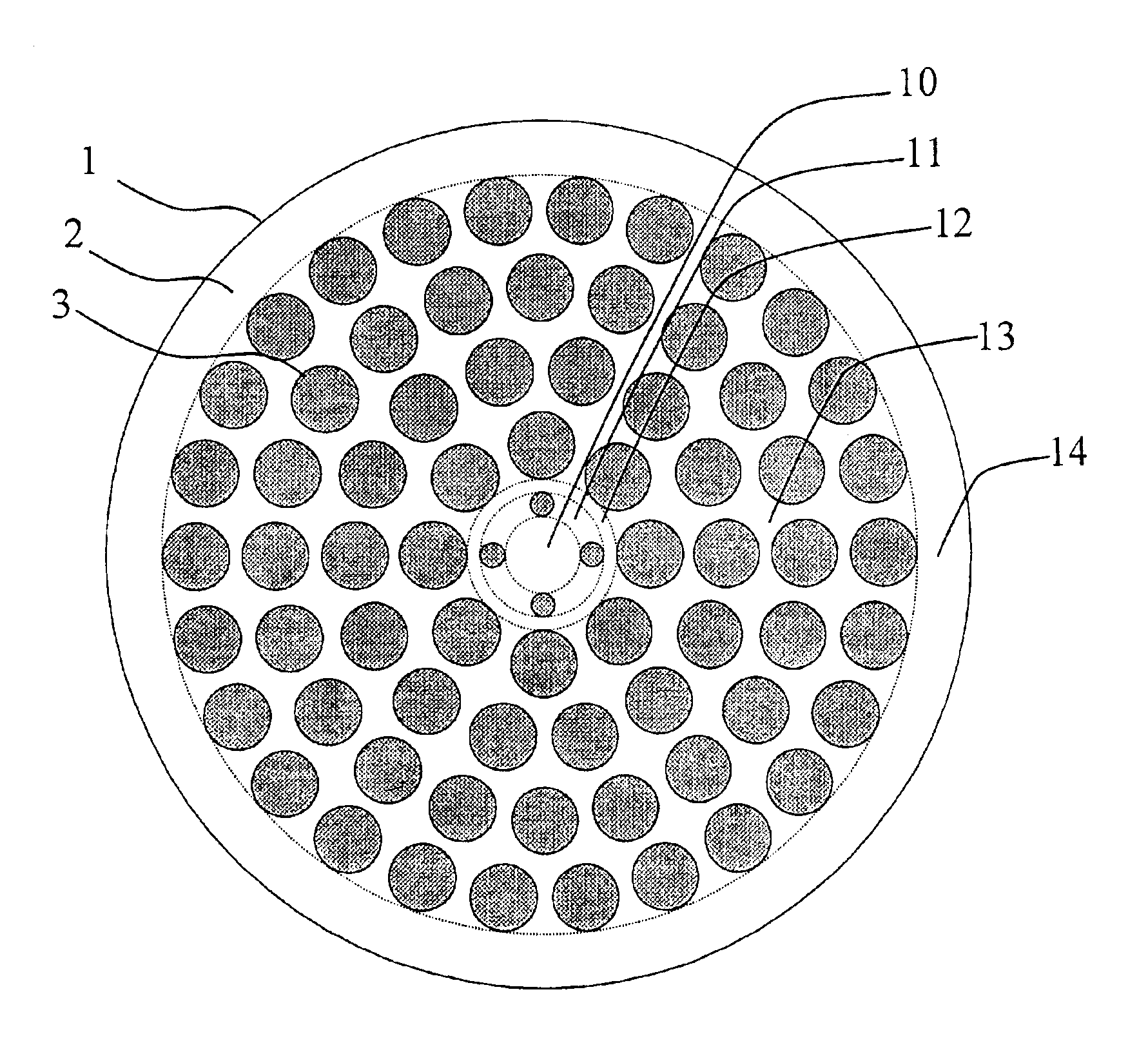
[0024]FIG. 1 is an illustration of a cross section taken perpendicular to the fiber axis of a microstructured optical fiber in accordance with the present invention. A plurality of holes 3, which are sub media, are arranged in silica glass 2, which is a main medium. The silica glass is typically free from impurities. However, it is also favorable to add dopants such as germanium, fluorine, chlorine, boron, aluminum, and titanium to silica glass and form a refractive index profile within the cross section of the optical fiber. As a result, it becomes possible to maintain waveguiding function even if the holes are collapsed. Such collapses are often caused in fusion splices of the optical fiber with other optical components, so that optical loss at a fusion splice can be suppressed by the waveguiding index profile. Also, by adding germanium to silica glass and exposing the optical fiber to UV radiation, it becomes possible to form fiber gratings and realize optical filters and optical...


PUM

PropertyMeasurementUnit
Diameteraaaaaaaaaa
Lengthaaaaaaaaaa
Areaaaaaaaaaaa

Abstract

A microstructured optical fiber is structured with a core region and a plurality of cladding regions surrounding the core region. Chromatic dispersion is relatively flat over a broad wavelength range with a small effective area, without need for air holes that are unacceptably small. An enlarged effective core area is obtained by selectively closing the holes in the innermost cladding, which holes are smaller and easier to close than the holes in other regions.

Description

FIELD OF THE INVENTION[0001]The present invention relates to microstructured optical fibers, more particularly to such optical fibers that realize flat dispersion and small effective core areas.BACKGROUND[0002]The recent development of the microstructured optical fiber, in which a high index core region is surrounded by cladding having a mix of silica and air, offers new fiber properties by virtue of the large refractive-index contrast that exists between glass and air. Appropriate design of microstructured optical fiber can realize flat dispersion characteristics. For example, as described in Designing the properties of dispersion-flattened photonic crystal fibers, Ferrando et al., OPTICS EXPRESS pp. 687-697 (2001), it is possible to realize dispersion characteristic D(λ) satisfying: maxλ∈Ω⁢[D⁡(λ)]-minλ∈Ω⁢[D⁡(λ)]≤Δ⁢ ⁢D,and⁢ ⁢minλ∈Ω⁢[D⁡(λ)]<D0<maxλ∈Ω⁢[D⁡(λ)],in a wavelength range Ω={λ|λ|≦λ2} where λ1≡1.3 [μm], λ2≡1.8 [μm], λ2−λ1=523 [nm], ΔD=2 [ps / nm / km], and D0=0 [ps / nm / km]. ...

Claims


Application Information

Patent Timeline
IPC IPC(8): C03B37/00C03C13/04C03C13/00G02B6/02G02B6/26G02B6/036G02B6/028
CPCC03C13/04G02B6/02028G02B6/02233G02B6/02242G02B6/02333G02B6/02357G02B6/02361G02B6/02376G02B6/02G02B6/028
Inventor HASEGAWA, TAKEMI
Owner SUMITOMO ELECTRIC IND LTD
Why Eureka
Try Eureka