Interpolator

a signal interpolator and interpolator technology, applied in the field of signal interpolators, can solve the problems of inability to use a single phase locked loop (pll) to generate both of the above frequencies, inability to achieve the effect of generating the output frequency of the pll, and inability to achieve the effect of greater flexibility

Inactive Publication Date: 2005-07-05
AVAGO TECH WIRELESS IP SINGAPORE PTE
View PDF3 Cites 9 Cited by
  • Summary
  • Abstract
  • Description
  • Claims
  • Application Information

AI Technical Summary

Benefits of technology

[0014]The objects, features and advantages of the invention include greater flexibility in enabling different frequencies to be matched, without requiring dynamic correction of an increment value.

Problems solved by technology

However, there is an inherent incompatibility in the signal timings for the two standards.
It is not practical to use a single Phase Locked Loop (PLL) for generating both of the above frequencies, as it would have to operate at a common divisor of the two frequencies, the desired frequency being generated by varying the multiplication factor inside the PLL.
Such high multiplication factors make the output frequency from the PLL very unstable.
Moreover, a PLL with such a high multiplication factor is extremely difficult to implement in an integrated circuit due to noise and isolation problems.
However, such an NCO is only capable of generating accurate timings for frequency relationships which can be related by 2m and STEP.
Therefore, it is not possible to use the fractional interpolator 16 and the NCO 18 to generate the desired frequencies accurately.
However, such a circuit inherently has a significant degree of jitter, and relies on an error responsive control signal to dynamically “correct” the incorrect timings from the NCO.
For the same reasons as those discussed previously, such a multiplication factor results in a high degree of jitter, and makes the PLL 108 very difficult to integrate into an integrated circuit.
However, there are no suitable integer values of STEP and 2m which satisfy the frequency relation of (272 / 47).

Method used


Image

  • Interpolator
  • Interpolator
  • Interpolator

Examples


Embodiment Construction

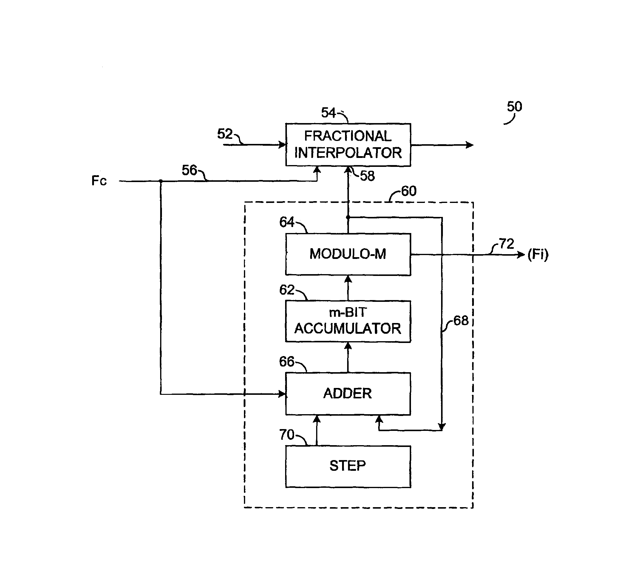
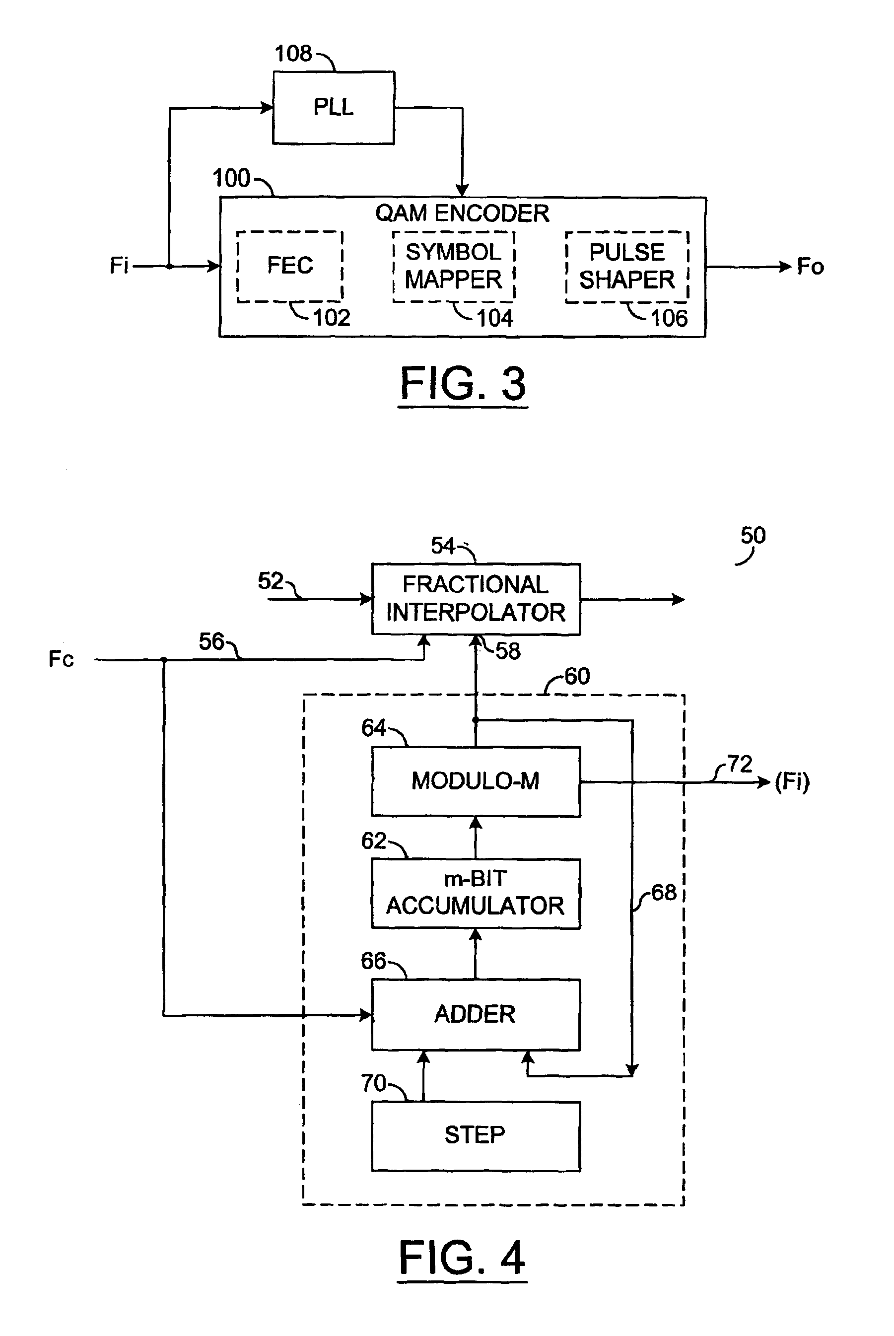
[0023]FIG. 4 shows the basic building blocks of a signal interpolator in a first embodiment. The purpose of the circuit 50 in this embodiment is to enable the circuit 50 operating from a certain clock frequency (e.g., Fc) to be able to extract and process data related to a different clock frequency (e.g., Fi).

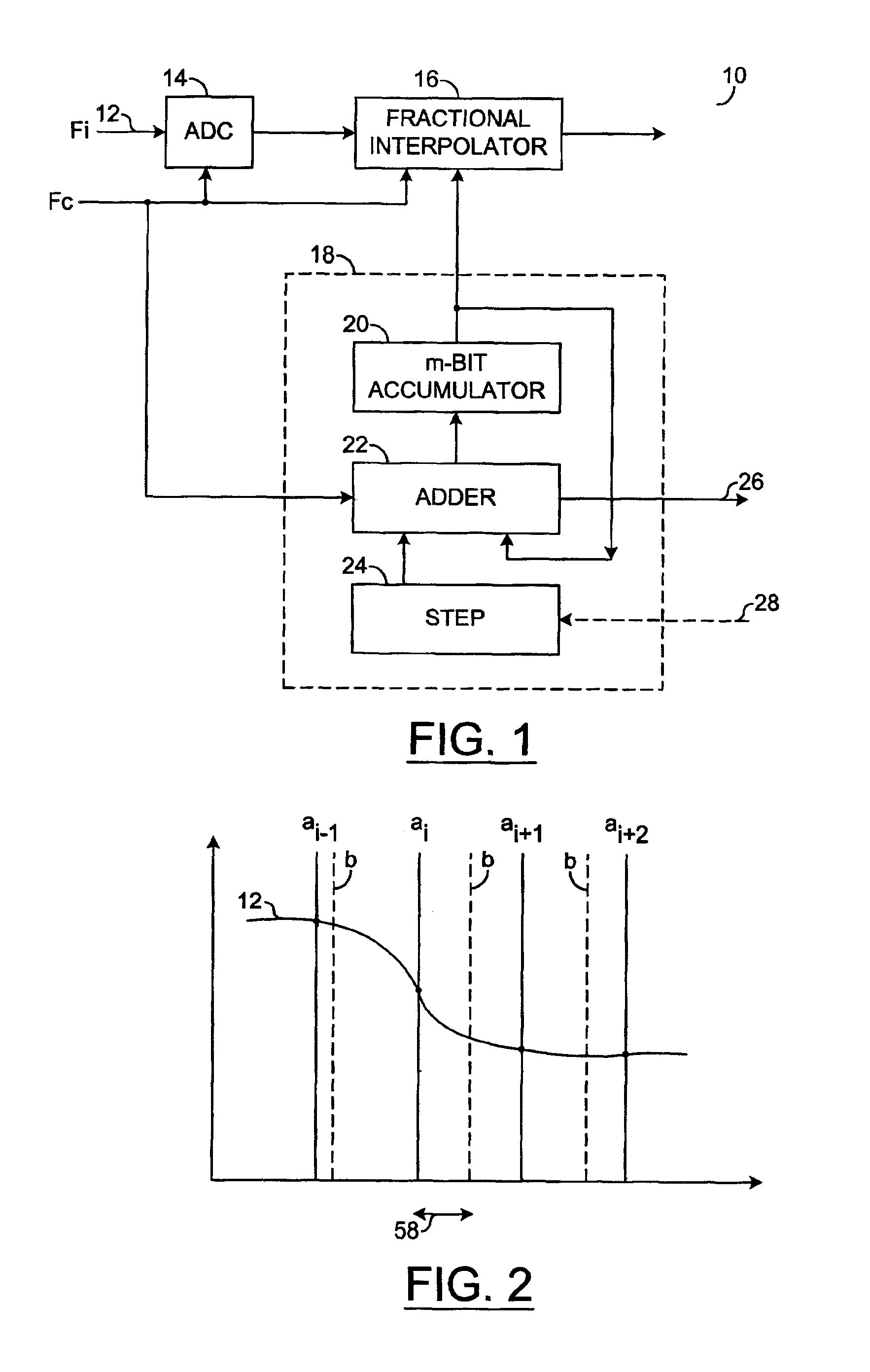
[0024]The circuit 50 is clocked at the circuit clock frequency Fc, and the circuit receives digitised values of an input signal 52 also sampled using the same circuit clock frequency Fc. The digitised samples are fed to a fractional interpolator 54 for re-calculating (interpolating) the digitised samples according to different timings matched to the clock frequency Fi. The fractional interpolator 54 has a clock signal input 56 for receiving the circuit clock frequency Fc, and a digital control input 58 for controlling the timing at which a new sample is calculated relative to two consecutive samples of the input signal 52. Referring to FIG. 2, the magnitude of the digital contr...


PUM


Abstract

A signal interpolator comprises a fractional interpolator and a numeric controlled oscillator. The numeric controlled oscillator may generate a control signal for controlling the fractional interpolator. The numeric controlled oscillator generally comprises a register, a modulo-M device, and an adder. The register may hold a count value, and the modulo-M device may apply a modulo-M function to the count value to generate the control signal therefrom. The adder may add an increment value to the modulo-M signal from the modulo-M device, to update the count value in the register.

Description

FIELD OF THE INVENTION[0001]The present invention relates to a signal interpolator, in particular, using fractional interpolation, for example, to enable processing of a first signal based on a first clock rate, by circuitry operating at a second clock rate. The invention is especially, but not exclusively, suitable to be implemented in an integrated circuit.[0002]A particular application of the invention is in the field of mobile telecommunications, for a processor capable of operating in both Time Division Synchronous Code Division Multiple Access (TD-SCDMA) and Global System Mobile (GSM) modes, these modes relying on different, incompatible clock frequencies. Another application is the field of signal encoders, for example, quadrature amplitude modulation (QAM) encoders. However, the invention is not limited exclusively to such applications.BACKGROUND TO THE INVENTION[0003]It is desirable that TD-SCDMA systems support GSM as well as the new TD-SCDMA standard. However, there is an...

Claims


Application Information

Patent Timeline
Patent Type & Authority Patents(United States)
IPC IPC(8): G06F7/38G06F17/17G06F7/68H03L7/06H04L7/00H04L27/38
CPCG06F7/68H04L27/38H03L7/06H04L7/0029H04L7/0079H04L7/0091
Inventor MUELLER, DETLEF
Owner AVAGO TECH WIRELESS IP SINGAPORE PTE
Why Eureka
Try Eureka