
Automatic speed change apparatus

a technology of automatic speed change and gear tooth, which is applied in mechanical devices, transportation and packaging, and gear teeth, etc., can solve the problems of reducing the efficiency of transmission, reducing the axial length, so as to reduce the length

Inactive Publication Date: 2005-07-12
OHKUBO MASAHIRO
View PDF11 Cites 9 Cited by
  • Summary
  • Abstract
  • Description
  • Claims
  • Application Information

AI Technical Summary

Benefits of technology

[0017]A first object of the present invention is to provide a front-wheel-drive speed change apparatus which comprises an input shaft, an intermediate shaft and an output shaft arranged in parallel, the output shaft being provided with a differential gear, and in which planetary gear sets are used for providing an input to a ring gear to afford first to fourth forward speeds that are frequently used, and the gear faces are reduced in load, the apparatus being improved in efficiency, smaller in gear steps than is the case with four-speed automatic speed change devices presently available, a least 5 in overall gear ratio range, and made available as a six-forward-speed, one-reverse-speed automatic speed change apparatus which is greatly shortened in the axial direction so as to give increased rigidity to the side members of the vehicle body almost without entailing any increase in cost to ensure a lower fuel consumption and improved safety from collisions of motor vehicles.
[0019]A third object of the invention is to use three counter gear sets to ensure increased freedom to determine gear ratios, the three gear sets being provided with radial bearings of enhanced strength to achieve a higher efficiency and improved durability and to ensure reduced noise.
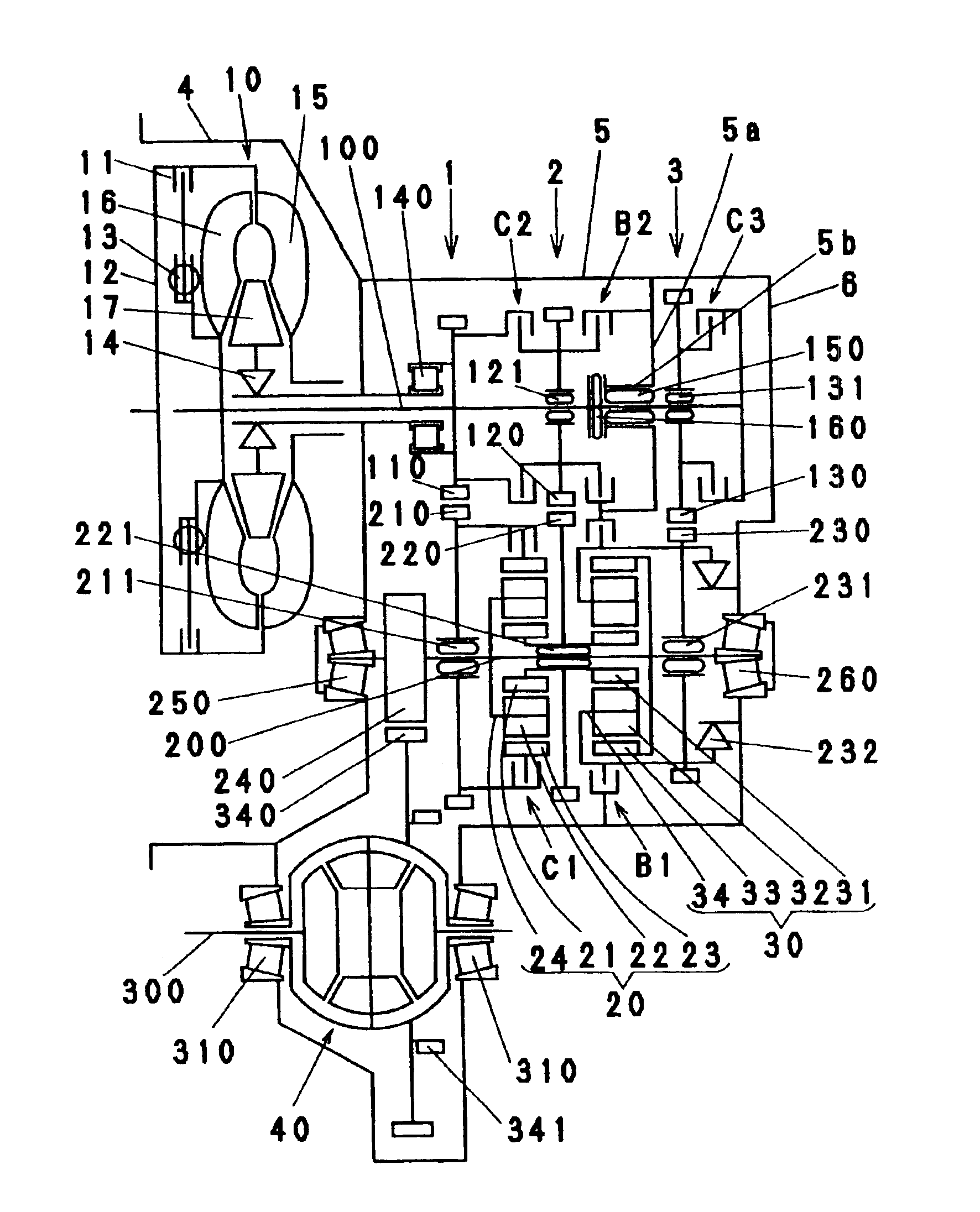
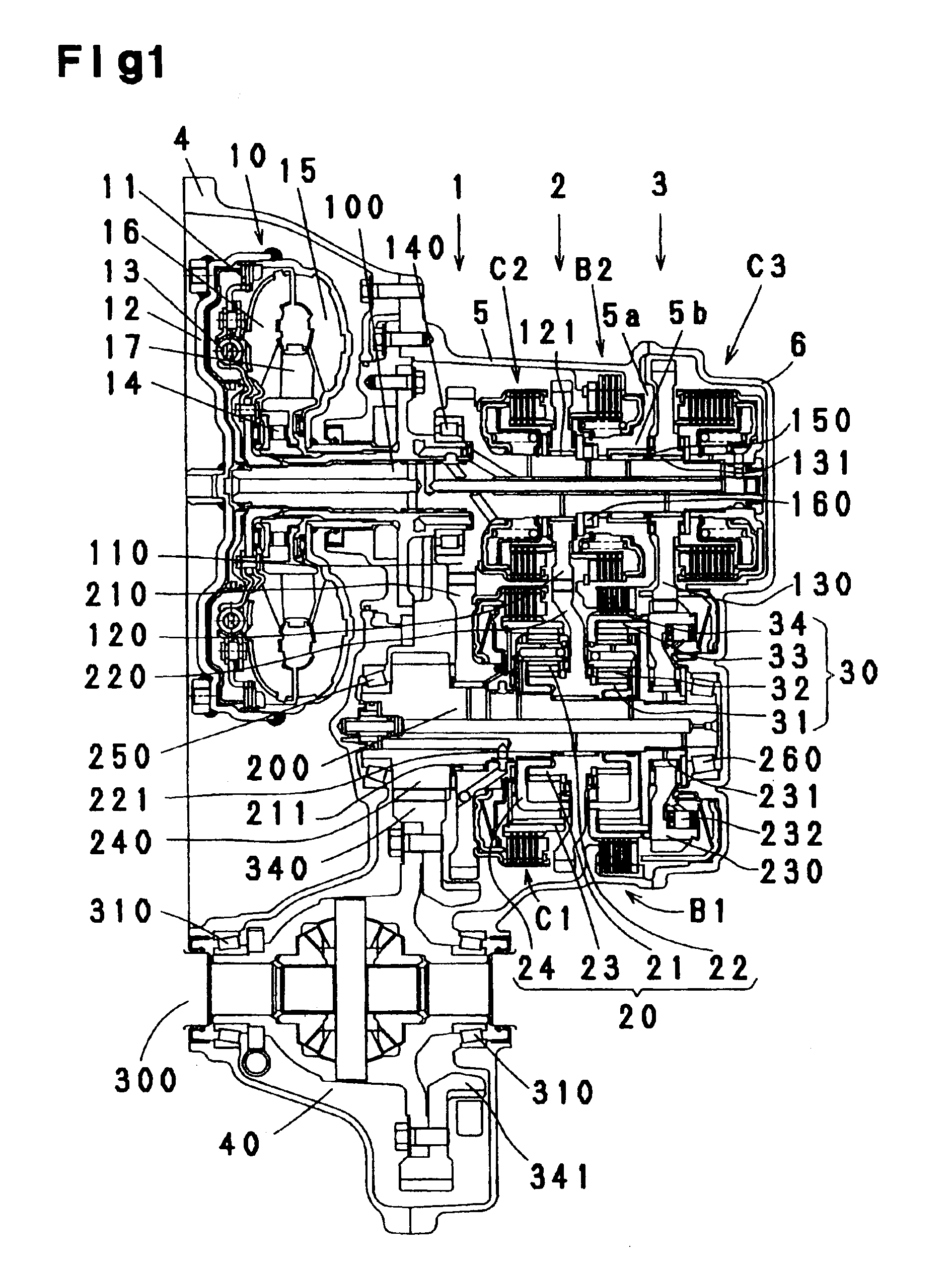
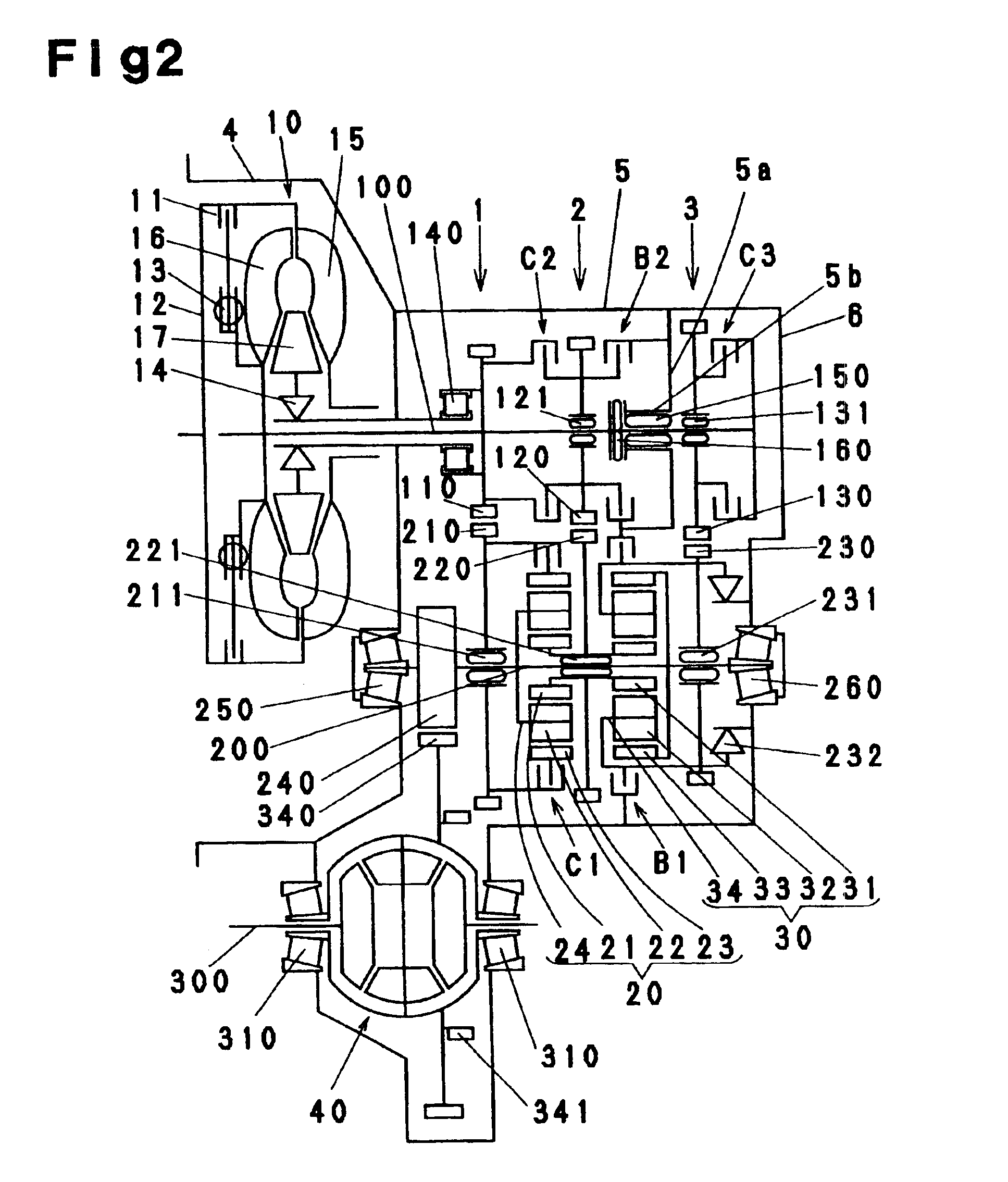
[0023]The first, second and third counter gear sets, each comprising two gears in mesh with each other, are so supported as described below for providing the first, second and third drive paths. The counter gear on the first shaft of the first counter gear set is integral with the first shaft, and the counter gear on the second shaft meshing with the above counter gear is rotatably held by a needle roller bearing on the second shaft, the counter gear on the first shaft of the second counter gear set is rotatably held by a needle roller bearing on the first shaft, and the counter gear on the second shaft meshing with this counter gear is rotatably held by a needle roller bearing on the second shaft, the counter gear on the first shaft of the third counter gear set is rotatably held by a needle roller bearing on the first shaft, and the counter gear on the second shaft meshing with this counter gear is rotatably held by a needle roller bearing on the spline hub integral with the ring gear of the second planetary gear set, the ring gear having the splined bore opposite end portions fitting around the second shaft so as to be coaxial therewith, the counter gear of the first counter gear set integral with the first shaft has an inner periphery thereof supported by a cylindrical roller bearing on a support fixed to a housing of the speed change apparatus to thereby support the first shaft, and the first shaft is supported by a boss portion integral with the housing of the speed change apparatus by means of needle roller bearings, and the second shaft has opposite ends thereof supported respectively by tapered roller bearings on a torque converter housing and a rear cover which are fixed to the housing of the apparatus. This shortens the axial length of the apparatus, further realizing a bearing arrangement of high strength.
[0026]Inlets to the first shaft of first and second oil channels for guiding a hydraulic oil to the clutches C2, C3 on the first shaft are formed by circumferential grooves in an outer periphery of the first shaft and three rotating seal rings around the outer periphery and in contact with an inner peripheral portion of the support fixed to the housing of the speed change apparatus, an inlet to the first shaft of an third oil channel for guiding a supply oil of low pressure to bearings, etc. arranged for the first shaft is formed in side portions of the support and the counter gear integral with the first shaft, by one rotating seal ring in contact with an inner peripheral portion of the counter gear and disposed around the support for the cylindrical roller bearing, a circumferential groove formed in the outer periphery of the first shaft and a rotating seal ring adjacent to above-mentioned one rotating seal ring, and an inlet to the second shaft of an fourth oil channel for guiding a hydraulic oil to the clutch C1 on the second shaft and an inlet to the second shaft of an fifth channel for guiding a supply oil of low pressure to bearings, etc. arranged for the second shaft are formed in a stepped bore formed in the second shaft at one end thereof, closer to the torque converter, where the tapered roller bearing is positioned, the inlets being defined by two rotating seal rings which are provided around an outer periphery of stepped portion of a channel-attached member fastened to the torque converter housing and which are in contact with respective two portions, having different diameters, of an inner periphery of the shaft end defining the stepped bore, the inlets being formed in an upper part of the stepped bore and in the center of the stepped bore. Thus, the inlets of oil for the shafts are all positioned at the junction of the apparatus housing and the torque converter housing, and the inlets of the oil channels are provided in shaft side faces. The housing and the first and second shafts can therefore be shortened.

Problems solved by technology

However, the apparatus then has the drawbacks of becoming more complex, lower in transmission efficiency, more costly and greater in axial length.
Nevertheless, the planetary gear set wherein the input is given to a sun gear, and the load on the gear tooth faces is great because of a small diameter is used in the four-forward-Speed, one-reverse-speed automatic speed change apparatus in place of the above arrangement because the single drive path to be additionally installed in the apparatus will interfere with the above gear train arrangement.
The apparatus requires only one additional clutch, whereas if the elements of the apparatus are arranged concentrically on the first shaft, this imposes a limitation on the shortening of the axial length of the apparatus partly because of the additional provision of the single drive path.
Although the four-forward-speed, one-reverse-speed automatic speed change apparatus is an improvement over three-forward-speed, one-reverse-speed automatic speed change apparatus, the overall gear ratio range obtained by dividing the gear ratio of first speed by the gear ratio of the fourth speed is as small as about 4, while the individual gear steps need to be great, so that the use of the engine at low speeds and the use of lockup of the torque converter for an improved fuel consumption still remain insufficient.
The disclosed apparatus further has the drawback of being elongated in the axial direction because the bearings for counter gears are retained on a housing and also because three clutches are arranged on a first shaft serving as the input shaft.
Further in the case where the bearings for the counter gears are held by the housing which is at rest, this mode of supporting the bearings is disadvantageous with respect to efficiency, durability and noise because the bearings are rotating at all times.

Method used


Image

  • Automatic speed change apparatus
  • Automatic speed change apparatus
  • Automatic speed change apparatus

Examples


embodiments

[0100]FIGS. 6, 7 and 8 show a first embodiment of the invention.

[0101]With reference to FIG. 6, the reciprocals α1, α2, α3 of reduction gear ratios of the first, second and third counter gear sets 1, 2, 3 providing the first, second and third drive paths are:

[0102]α1=0.628

[0103]α2=0.687

[0104]α3=1

[0105]Thus, the counter gear set 3 is the smallest in reduction gear ratio, and the counter gear set 1 is set at a slightly greater value than the counter gear set 2 in this ratio. Further with the planetary gear sets, the tooth number ratios ρ1, ρ2 of the first and second planetary gear sets 20, 30, each obtained by dividing the number of teeth of the sun gear by the number of teeth of the ring gear, are:

[0106]ρ1=0.552

[0107]ρ2=0.463

[0108]Thus, the first planetary gear set 20 is set at a slightly greater value.

[0109]FIG. 7 is a speed diagram of the first embodiment prepared according to the meshing law of planetary gears. The positions of the first to fourth elements of the first and second ...


PUM


Abstract

An automatic speed change apparatus including an input shaft, an intermediate shaft and an output shaft arranged in parallel. The input shaft is coupled to the intermediate shaft by counter gear sets providing first, second and third drive paths. The input shaft is provided with clutches for engaging or disengaging the second and third drive paths and with a brake. The intermediate shaft is provided with a clutch, a brake and a one-way clutch for engaging, disengaging or braking the first and third drive path and with planetary gear sets. The first drive path is coupled to a ring gear, the second drive path is coupled to sun gears, and the third drive path is coupled to a planetary carrier. A planetary carrier and a ring gear are connected to the intermediate shaft, and the intermediate shaft is coupled to the output shaft by a fourth counter gear set.

Description

BACKGROUND OF THE INVENTION[0001]1. Field of the Invention[0002]The present invention relates to automatic speed change apparatus wherein drive paths connected to a plurality of elements of planetary gear sets are controlled by hydraulic clutches and brakes and, more particularly, to a front-wheel-drive automatic speed change apparatus comprising an input shaft, an intermediate shaft and an output shaft which are arranged in parallel, with a differential gear provided on the output shaft.[0003]2. Description of the Related Art[0004]Four-forward-speed, one-reverse-speed speed change apparatuses are known which have incorporated therein a torque converter having a lockup clutch as passenger motor vehicle automatic transmissions which are most prevalently used. Front-wheel-drive four-forward-speed, one-reverse-speed automatic speed change apparatuses generally comprise a first shaft coaxial with an engine and provided via a torque converter with three clutches, two brakes, two planetar...

Claims


Application Information

Patent Timeline
Patent Type & Authority Patents(United States)
IPC IPC(8): F16H3/66F16H37/02F16H3/44F16H37/04
CPCF16H3/66F16H37/04Y10T74/19223F16H2200/2007F16H2200/0052
Inventor OHKUBO, MASAHIRO
Owner OHKUBO MASAHIRO
Learn More