Mashing process

a technology of filtration process and mash, which is applied in the field of mash, can solve the problems of limiting the fine parts of the malt grist, not desirable in the brewing process, and preventing the utilization of the filtration process so far

Inactive Publication Date: 2005-07-12
PALL CORP
View PDF33 Cites 11 Cited by
  • Summary
  • Abstract
  • Description
  • Claims
  • Application Information

AI Technical Summary

Benefits of technology

[0005]It is the aim of each of those mashing processes to achieve a high yield (dissolution of all soluble components). After the separation process, the wort should be as free of particles as possible, so that the following steps of beer preparation progress in a controlled and regular manner. Of special importance in this context are low β-glucane contents with regard to the filterability of the future beers and low polyphenol and anthocyanogene contents with regard to the beer's color, taste and colloidal stability.
[0084]The following surprising results have been obtained with the present invention, which are explained in more detail by means of examples, and a technically and economically improved process for the filtration of mash has been created. With this process, where a dynamic cross-flow filtration system is used for the filtration of the mash, it has furthermore turned out that totally new possibilities for the control and variation of the beer itself are facilitated by a simple adjustment of particular parameters with the mash filtration.

Problems solved by technology

A disadvantage of the filtration processes described so far is the necessity to carry out the grinding of the utilized fruit only up to a certain lower limit for the particle size.
Such a limitation of the fine parts in the malt grists is, however, not desirable in terms of the brewing process.
While the cross-flow filtration systems should be basically suited for use in the lautering of mash from finely ground malt, in practice, however, problems arise, which have impeded the utilization of this filtration process so far.
Furthermore, pressure differences on the surface of the filter cause pressure gradients, which may block the filter.
And whenever such pressure differences are particularly marked, they may cause the wort already filtered to flow back through the filter medium, which clearly decreases the efficiency of the process.

Method used


Image

  • Mashing process
  • Mashing process
  • Mashing process

Examples


Embodiment Construction
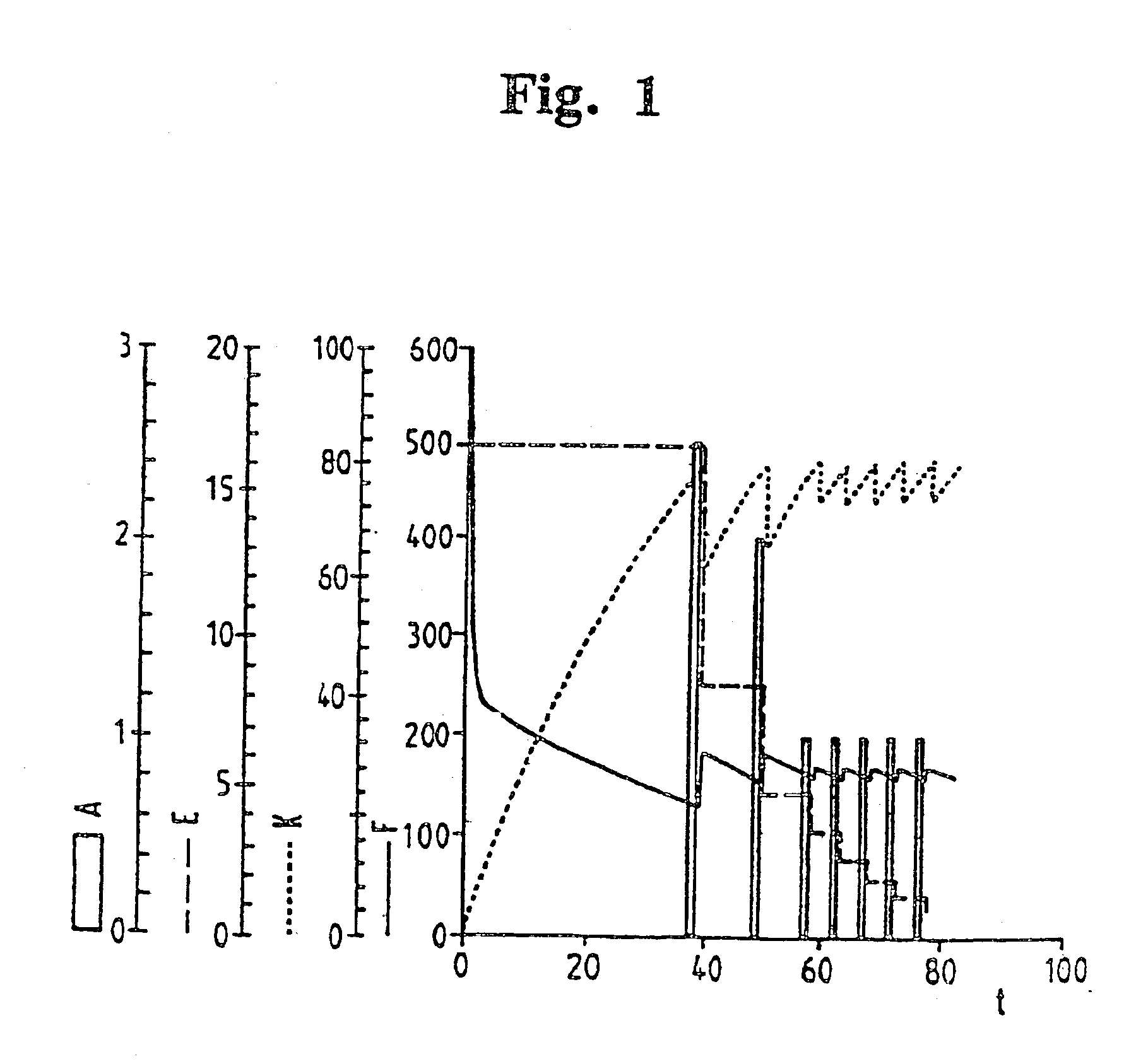
Mashing Process

[0100]The standardized Eyben-mashing process was used for obtaining this data. The temperature grids for the mashes are 45° C., 62° C. and 70° C. for 30 minutes, heating up with 1° C. / min each. Towards the end of the mashing process, the temperature was raised to 78° C. and the mash was separated by means of a dynamic cross-flow filtration system and, for comparison, with conventional lauter tun processes.

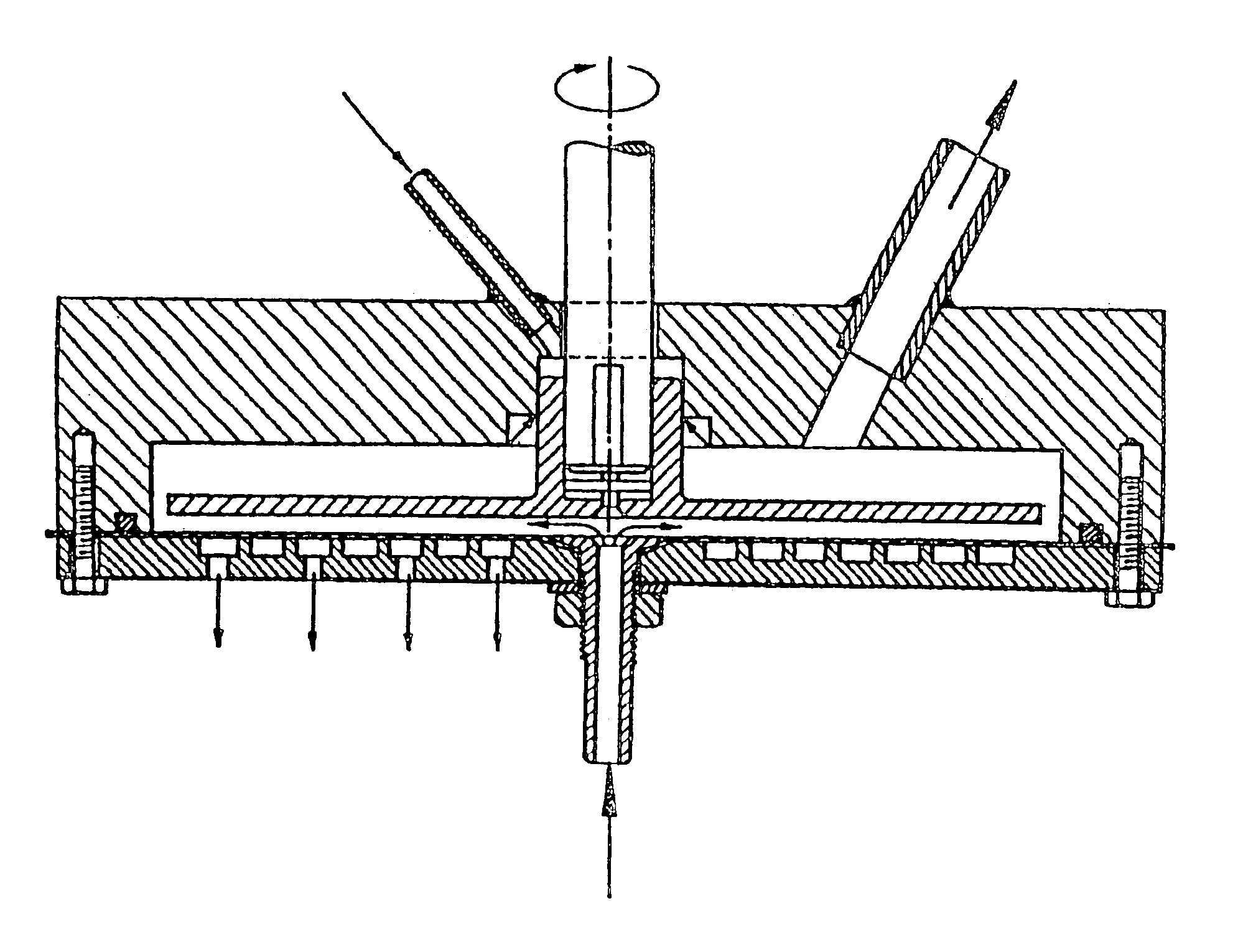
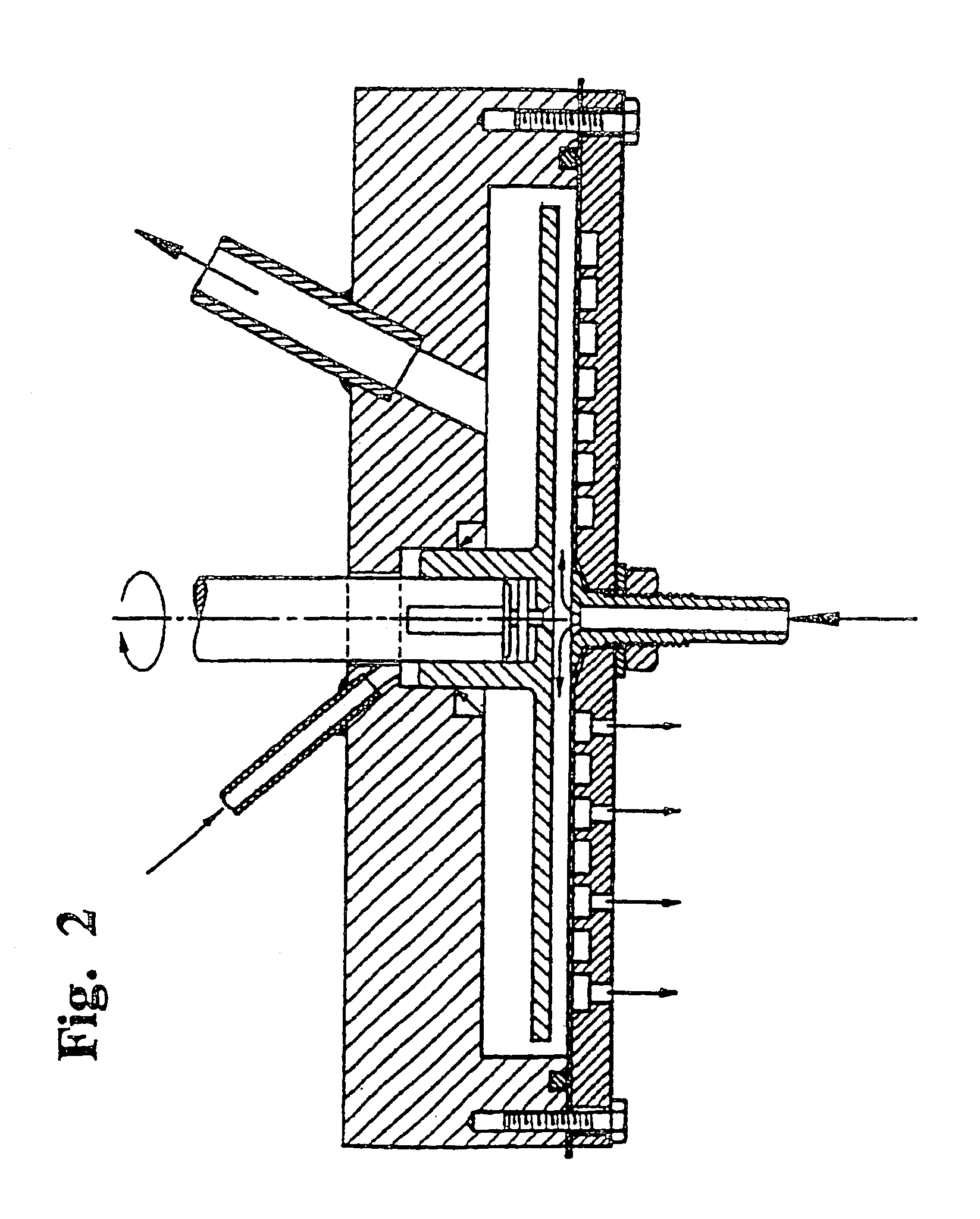
Wort-Flow with Dynamic Cross-Flow Filtration Systems

[0101]FIG. 1 gives a typical example for the lautering of mash and edulcorating of the spent grain by dynamic cross-flow filtration. Here, a PTFE membrane with an absolute retention rate of 0.1 μm was used. The average filtrate flows were 180 l / hm2. The results were obtained using a husk-reduced powder grist (all fractions smaller than or equal to 100 μm, size distributions, see Table 3). In the literature (Schuster, Weinfurtner, Narziss (1985)) for typical malt grist according to Table 1 average filtrate flows are ...


PUM

PropertyMeasurementUnit
grain sizeaaaaaaaaaa
particle size distributionaaaaaaaaaa

Abstract

Specification discloses the use of a dynamic cross-flow filtration system for the filtration of mash. Also disclosed are a mashing process, wherein mash is filtered and wort is obtained, and a process for the preparation of beer, as well as apparatuses and devices for performing one or more of these process.

Description

[0001]This application is a continuation of U.S. application Ser. No. 09 / 639,660, which was filed on Aug. 16, 2000, and is now abandoned and which was a continuation of U.S. application Ser. No. 09 / 480,141, filed Jan. 10, 2000 which is now abandoned and was a continuation of U.S. application Ser. No. 09 / 319,026, filed Jul. 29, 1998 which is now abandoned and was the national phase of International application No. PCT / EP97 / 06490, which was filed on Nov. 20, 1997, and which claimed priority of Germany Application No. 196 49 661.6, which was filed on Nov. 29, 1996, all of which are incorporated by reference.[0002]The invention relates to processes for mashing. In addition, the invention relates to special mash filter devices and processing devices, as well as their use.[0003]Mashing is an important process step in the preparation of beer. Here, the solid starting material malt, and the grist ground therefrom in a defined way, respectively, are subjected to a dissolution process with wa...

Claims


Application Information

Patent Timeline
Patent Type & Authority Patents(United States)
IPC IPC(8): C12C7/00C12C7/16
CPCC12C7/16C12C7/163C12C7/165
Inventor LOTZ, MARKUSRANDHAHN, HORSTBERNDT, ROLFMULLER, GEBHARDT
Owner PALL CORP
Why Eureka
Try Eureka