Power control for a switching mode power amplifier

a power amplifier and switching mode technology, applied in the direction of automatic tone/bandwidth control, tone control, gain control, etc., can solve the problem of limiting the dynamic range achieved by varying the power supply to the switching mode power amplifier mentioned above, and inherently very non-linear, so as to achieve linear control of power level, preserve the efficiency of the switching mode power amplifier, and achieve higher power levels

Inactive Publication Date: 2005-07-12
NOKIA TECHNOLOGLES OY
View PDF12 Cites 111 Cited by
  • Summary
  • Abstract
  • Description
  • Claims
  • Application Information

AI Technical Summary

Benefits of technology

[0016]It is an advantage of the invention that it provides an alternative to known approaches for a power control of a switching mode amplifier.
[0017]It is further an advantage of the invention that it enables a linear control of the power level at the output of a switching mode power amplifier over a wide power range, while preserving the efficiency of the switching mode power amplifier at higher power levels.
[0018]It is further an advantage of the invention that it requires few or no extra radio-frequency components compared to a situation in which no power control is performed or in which the power control has a narrow range.
[0019]Preferred embodiments of the invention become apparent from the dependent claims.
[0020]The proposed method and the proposed structure can be employed for controlling only the output power level of the switching mode power amplifier, e.g. in case a constant-envelope signal is to be provided at the output of the switching mode amplifier.
[0021]In a preferred embodiment, however, the proposed method and the proposed structure can be employed in addition for controlling an amplitude modulation of the signal output by the switching mode power amplifier. In this case, the required dynamic range has to cover both, the average power level variation and the desired amplitude variation. Thus, both, power level control and amplitude modulation are realized by adjusting on the one hand a power supply provided to the switching mode power amplifier at higher desired output power levels and on the other hand a pre-amplification of the input signal at lower desired output power levels.

Problems solved by technology

While a switching mode power amplifier can be very efficient, it is inherently very non-linear, i.e. the amplitude of its output signals are not affected linearly by a change of the amplitude of its input signals within the regular operating range.
Since a switching mode power amplifier is inherently very non-linear, however, a conventional power control is not suitable for a switching mode power amplifier.
On the other hand, the dynamic range that can be achieved by varying the power supply to the switching mode power amplifier mentioned above is restricted by a lower limit.
This lower limit results from a leakage of an input radio frequency signal through the transistor of the switching mode power amplifier due to its parasitic capacitances.
None of these documents, however, enables a linear power control for a switching mode power amplifier over a very large dynamic range while preserving the efficiency of the amplifier.

Method used


Image

  • Power control for a switching mode power amplifier
  • Power control for a switching mode power amplifier
  • Power control for a switching mode power amplifier

Examples


first embodiment

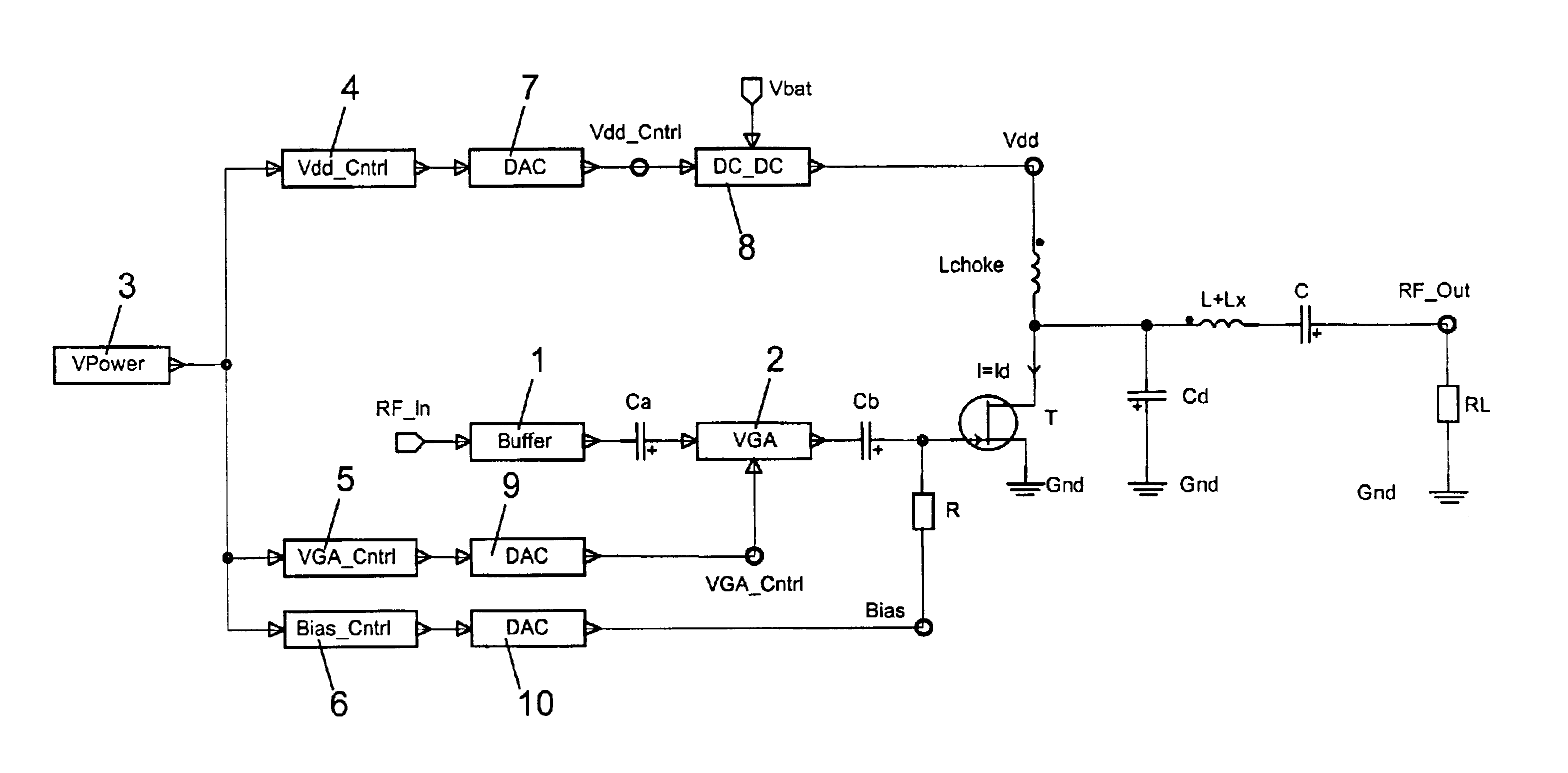
[0034]FIG. 1 is a schematic block diagram of a power control structure according to the invention. The structure can be for example a transmitter or a part of a transmitter which is employed for amplifying a constant envelope signal. The average power level of the amplified output signal has to be controllable over a large range.

[0035]The power control structure of FIG. 1 comprises a class-E switching mode power amplifier. The switching mode power amplifier includes a field effect transistor (FET) T. A voltage supply terminal of the switching mode power amplifier is connected via a choke coil Lchoke to the drain of the transistor T. The drain of the transistor T is further connected via a first capacitor Cd to ground Gnd and via a second coil L+Lx and a second capacitor C to the output RF_Out of the switching mode power amplifier. The output RF_Out of the switching mode power amplifier constitutes at the same time the output of the presented structure. The source of the transistor T...

second embodiment

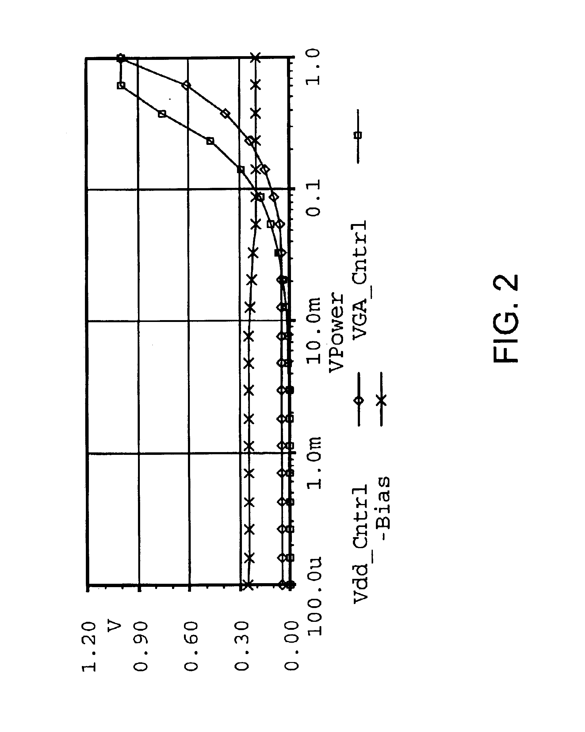
[0058]FIG. 6 is a schematic block diagram of a power control structure according to the invention. The power control structure depicted in FIG. 1 provides a possibility of changing the output power in decibels linearly as a function of a power control voltage VPower represented by a digital control word. The structure depicted in FIG. 6, in contrast, provides a possibility of changing the amplitude of the output signal linearly as a function of an additional amplitude control voltage VAmp represented by a digital control word. At the same time, a power control over a large range is still possible. The structure presented in FIG. 6 constitutes an extension of a conventional EER transmitter.

[0059]The structure of FIG. 6 comprises exactly the same components as the structure of FIG. 1, and these components are also arranged in exactly the same manner as in FIG. 1 except for the power control unit 3. Correspondingly, also the same reference signs as in FIG. 1 were assigned in FIG. 6 to ...


PUM


Abstract

The invention relates to a power control structure comprising a switching mode power amplifier for receiving an input signal, for amplifying the received input signal and for providing the amplified signal as output signal. In order to enable a power control over a large range while preserving the efficiency of the power amplifier, the structure further comprises a first control arrangement for controlling the power level of the output signal at least at higher desired power levels by adjusting a power supply provided to the switching mode power amplifier, and in addition a second control arrangement for controlling the power level of the output signal at least at lower desired power levels by adjusting the power of the input signal before it is provided to the switching mode power amplifier. The invention relates equally to a corresponding method.

Description

FIELD OF THE INVENTION[0001]The invention relates to a power control structure comprising a switching mode power amplifier for receiving an input signal, for amplifying a received input signal and for providing the amplified signal as output signal. The invention relates equally to a method of controlling at least a power level of an output signal of such a switching mode power amplifier.BACKGROUND OF THE INVENTION[0002]Switching mode power amplifiers are known from the state of the art as particularly efficient power amplifiers. Class-E amplifiers, for example, which have been presented in U.S. Pat. No. 3,919,656, are switching mode power amplifiers which can theoretically approach a power efficiency of 100%. Switching mode power amplifiers are used for example in transmitter architectures which require a low power consumption, like transmitter architectures employed for mobile devices.[0003]While a switching mode power amplifier can be very efficient, it is inherently very non-lin...

Claims


Application Information

Patent Timeline
Patent Type & Authority Patents(United States)
IPC IPC(8): H03F3/217H03F3/20H03F1/02
CPCH03F1/0227H03F3/2176H03F1/02H03F3/217
Inventor ROSNELL, SEPPOVARIS, JUKKA
Owner NOKIA TECHNOLOGLES OY
Why Eureka
Try Eureka