Anti-reflection film, polarizing plate comprising the same, and image display device using the anti-reflection film or the polarizing plate

a technology of anti-reflection film and polarizing plate, which is applied in the direction of polarizing elements, coatings, instruments, etc., can solve the problems of insufficient mass production of the method of forming a transparent matal oxide thin film by such vapor deposition, unsatisfactory production of anti-reflection film, and prone to surface defects

Inactive Publication Date: 2005-07-12
FUJIFILM CORP
View PDF23 Cites 91 Cited by
  • Summary
  • Abstract
  • Description
  • Claims
  • Application Information

AI Technical Summary

Benefits of technology

[0030]An object of the present invention is to provide an

Problems solved by technology

However, the method of forming a transparent matal oxide thin film by such vapor deposition has insufficient productivity for mass production.
However, there was a problem that the low-refractive-index layer described in the publication substantially consisted of only an inorganic compound, and therefore it was very fragile.
On the other hand, when an anti-reflection film is formed by applying, onto a substrate, a low-refractive-index layer as described, for example, in JP-A-2-245702, a problem arises that surface defects (pointing defects) are apt to occur, and consequently the thus-produced anti-reflection film is unsatisfactory.
However, STN-LCD has problems such as a slow response (several hundred milliseconds) and difficulty in gradation display, and is inferior in display characteristics to those of a liquid crystal display device using active element (such as TFT-LCD and MIM-LCD).
Since TN

Method used


Image

  • Anti-reflection film, polarizing plate comprising the same, and image display device using the anti-reflection film or the polarizing plate
  • Anti-reflection film, polarizing plate comprising the same, and image display device using the anti-reflection film or the polarizing plate
  • Anti-reflection film, polarizing plate comprising the same, and image display device using the anti-reflection film or the polarizing plate

Examples


embodiment 1

First Embodiment of the Invention (Embodiment 1)

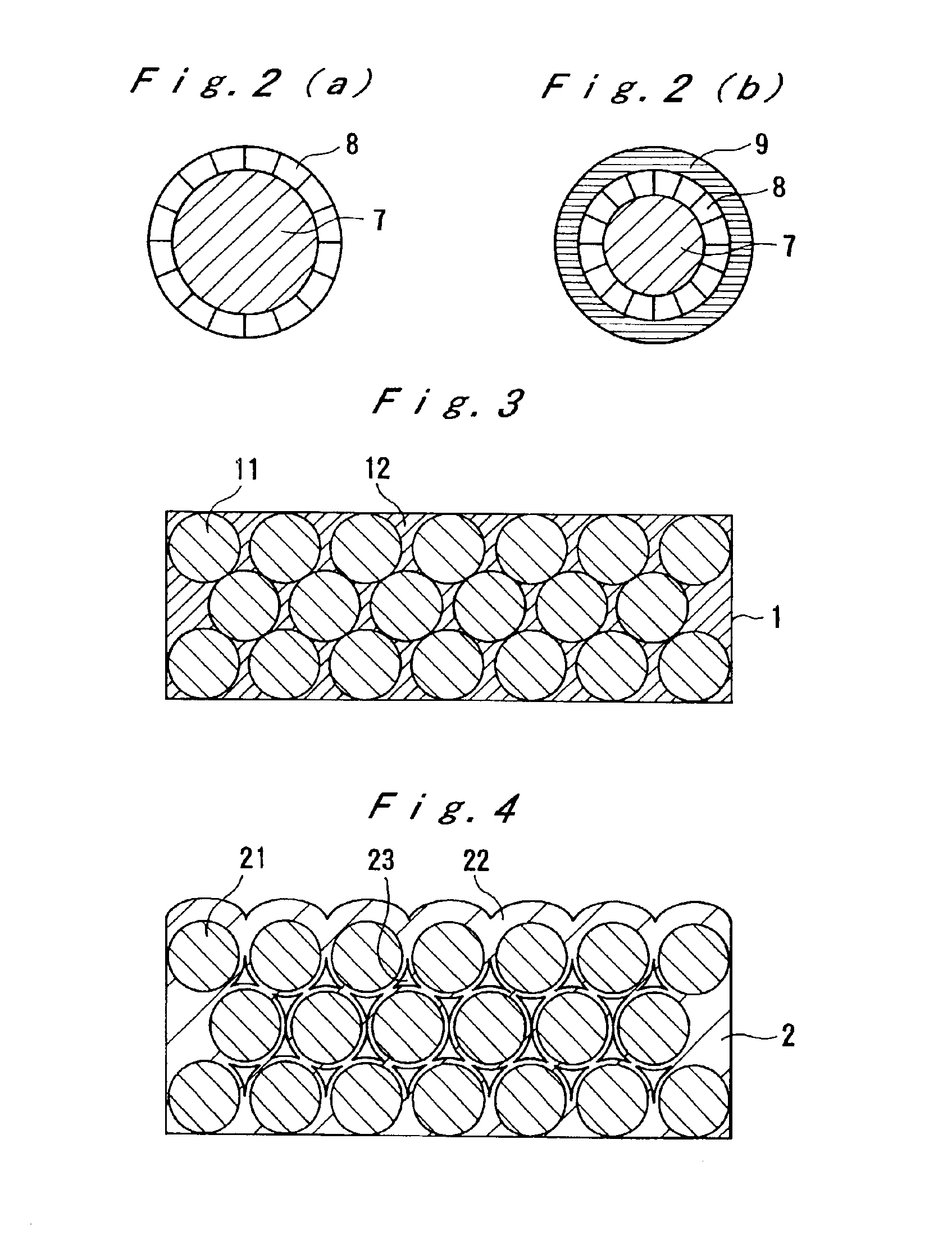
[0113]The following will describe a basic constitution of an anti-reflection film of the present invention, which has a low-refractive-index layer, and a high-refractive-index layer that comprises inorganic fine particles having a core composed mainly of titanium dioxide, and a shell composed mainly of an inorganic compound other than titanium dioxide, with reference to the attached drawings.

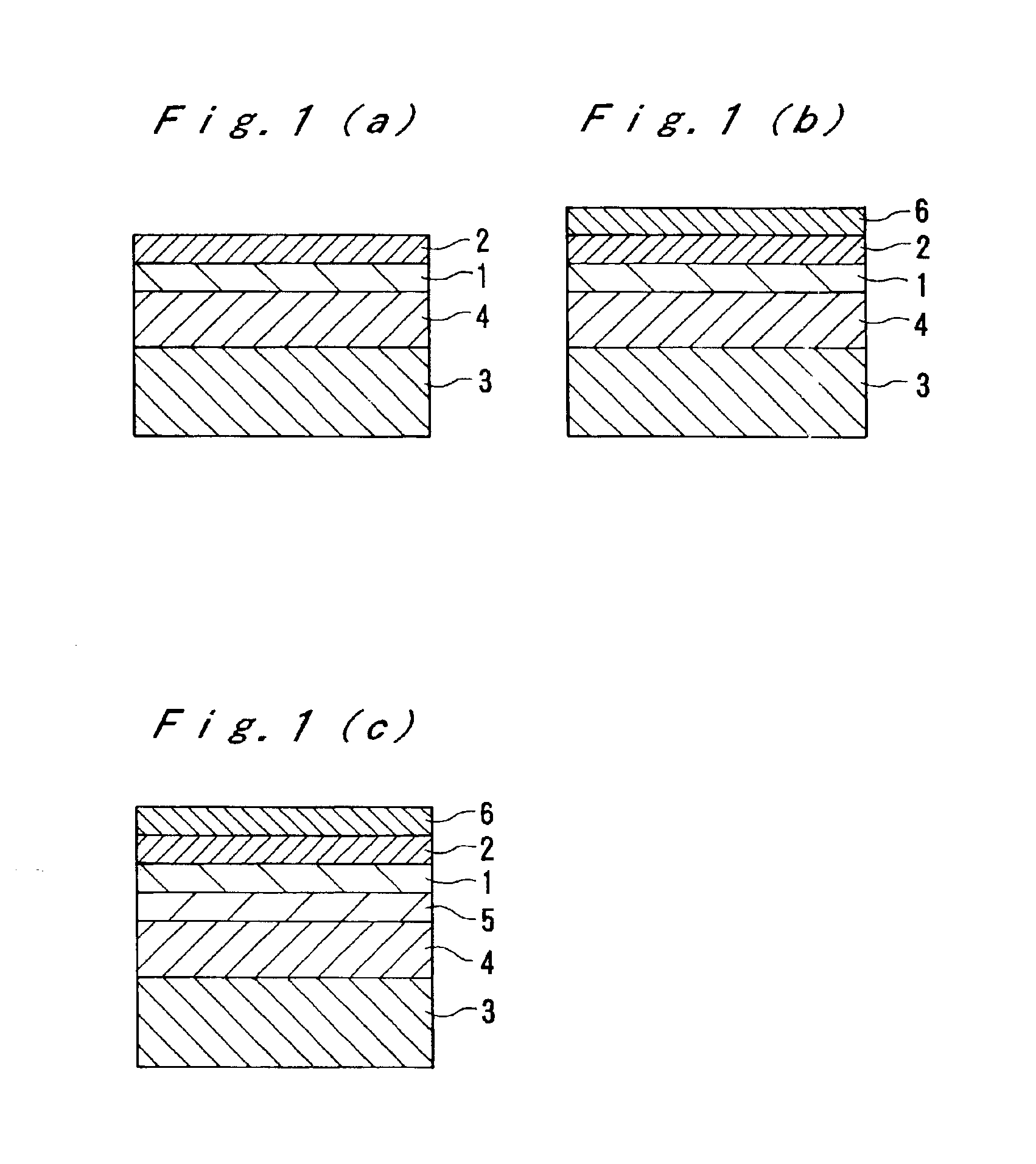
[0114]FIG. 1 is a schematic sectional view showing a main layer constitution of an anti-reflection film.

[0115]The embodiment shown in FIG. 1(a) has a layer constitution of a transparent support (3), a hard coat layer (4), a high-refractive-index layer (1), and a low-refractive-index layer (2), in this order. The transparent support (3), a high-refractive-index layer (1), and the low-refractive-index layer (2) have the refractive indices satisfying the following relationship.

Refractive index of high-refractive-index layer>Refractive index of transpa...

embodiment 2

Second Embodiment of the Invention (Embodiment 2)

[0315]The following will describe an anti-reflection film having a low-refractive-index layer, wherein fine voids are made between short fibrous inorganic fine particles, referring to drawings showing a basic constitution of the anti-reflection film.

[0316]FIGS. 7(a)-(d) are sectional schematic views showing a layer constitution of an anti-reflection film, when the anti-reflection film has multiple layers.

[0317]The embodiment shown in FIG. 7(a) has a layer constitution of a transparent support (103), a hard coat layer (102), and a low-refractive-index layer (101), in this order. The transparent support (103) and the low-refractive-index layer (101) have the refractive indices satisfying the following relationship.

Refractive index of transparent support>Refractive index of low-refractive-index layer

[0318]Further, in the case that an anti-reflection film is placed on the surface of a hard material as a glass (a screen surface of CRT, and...

embodiment 3

Third Embodiment of the Invention (Embodiment 3)

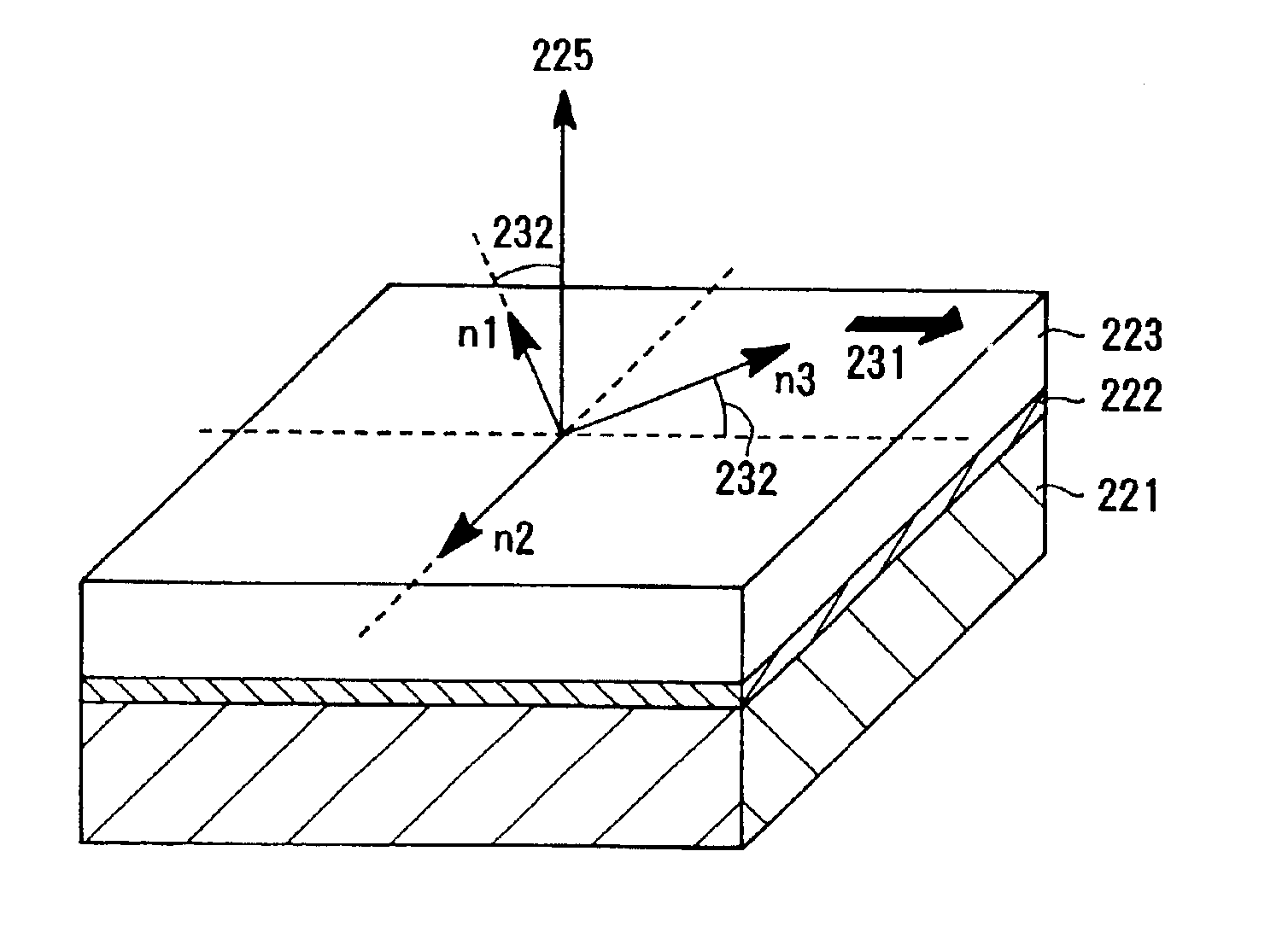
[0386]Referring to the drawings, the following will describe basic structures of polarizing plates having optical compensation capacity and anti-reflection ability of the present invention, and basic structures of image display devices, of a liquid-crystal-display type and a color-liquid-crystal-display type, having the polarizing plate.

[0387]FIG. 13 is an example of a schematic cross sectional view showing the layer construction of the optical compensative layer. The optical compensative layer has a layer construction of a transparent support 221, an alignment layer 222, and an optical anisotropic layer 223, in the written order. The optical anisotropic layer contains liquid crystall discotic compounds 224a, 224b and 224c, and their light axes have inclined angles of θa, θb, and θc with the direction of a normal line 225 of the transparent support. These inclined angles are increased from the transparent support side of the optical an...


PUM

PropertyMeasurementUnit
Lengthaaaaaaaaaa
Percent by massaaaaaaaaaa

Abstract

There is disclosed an anti-reflection film comprising 5-65% by volume of inorganic fine particles having an average particle size of 1-200 nm and having a core/shell structure, and 35-95% by volume of a polymer, wherein a high-refractive-index layer having a refractive index of 1.65-2.40 and a low-refractive-index layer having a refractive index of 1.30-1.55 are laminated. There is also disclosed a polarizing plate and image display device utilizing the anti-reflection film. The anti-reflection film is suitable for mass production.

Description

[0001]This application is a divisional application of application Ser. No. 09 / 671,634 filed on Sep. 28, 2000.FIELD OF THE INVENTION[0002]The present invention relates to an anti-reflection film, a polarizing plate having the same, and an image display device utilizing the anti-reflection film or the polarizing plate.[0003]Particularly, the present invention relates to an anti-reflection film that comprises a low-refractive-index layer, and a high-refractive-index layer, which comprises inorganic fine particles having a core composed mainly of titanium dioxide and a shell composed mainly of an inorganic compound other than titanium dioxide, or an anti-reflection film having a low-refractive-index layer in which fine voids exist between inorganic fine particles in a short fiber form.[0004]Further, the present invention relates to a polarizing plate that has optical compensation capacity and anti-reflection ability. The present also relates to a liquid crystal display type, or a color ...

Claims


Application Information

Patent Timeline
IPC IPC(8): G02B1/11G02B1/10G02B5/30G02F1/13G02F1/1335G02F1/13363
CPCG02B1/111G02B5/3033G02F1/133632G02F1/133502
Inventor NAKAMURA, KENICHIAMIMORI, ICHIROIKEYAMA, AKIHIROWATANABE, JUN
Owner FUJIFILM CORP
Why Eureka
Try Eureka