Motor vehicle electric system

Inactive Publication Date: 2005-07-19
CONTINENTAL AUTOMOTIVE GMBH
View PDF8 Cites 73 Cited by
  • Summary
  • Abstract
  • Description
  • Claims
  • Application Information

AI Technical Summary

Benefits of technology

[0057]The particular advantage of the invention lies in the fact that the expensive bi-directional DC/DC converter is replaced by four (in the 42 V/14 V “two voltage” vehicle electric system) or two (in the 42 V “single voltage” vehicle electric system) controlled switches. The voltage present at the ISG output (the voltage present at an intermediate circuit capacitor C) and/or the current flowing to or from the ISG can be controlled, so switching can be completed in a virtually zero-power state, which reduces the demands placed on the switches quite considerably.
[0058]The integrated starter-generator ISG is isolated from the battery during boosting and recuperation and is instead connected to the double lay

Problems solved by technology

It is technically expedient in this respect to limit the power output and also the generator output to no more than 3 kW, as otherwise the vehicle electric system currents would be too high.
One major problem is the cost-effective implementation of an energy storage mechanism able to manage the high charging and discharging currents over the long term.
This type of battery has a very limited cycling resilience, as the method it uses to transport energy, namely a transport of material (ions), entails notable losses.
What this means is that the structure of the electrodes changes continuously as the active surface shrinks (loss of capacity) and material is lost.
This loss of material leads to the deposition of lead sludge.
The battery loses capacity only slowly and accordingly has a lifetime of many years.
It is also technically difficult to ensure charging capacity for currents of up to 270 A at all times. The result of this is that the battery must be replaced as part of every scheduled service of the vehicle and possibly even between scheduled services if lead-acid batteries are used for boost and recuperation.
This is completely unacceptable.
A system with a 36 V lead-acid battery does have the lowest initial cost

Method used


Image

  • Motor vehicle electric system
  • Motor vehicle electric system
  • Motor vehicle electric system

Examples


Embodiment Construction

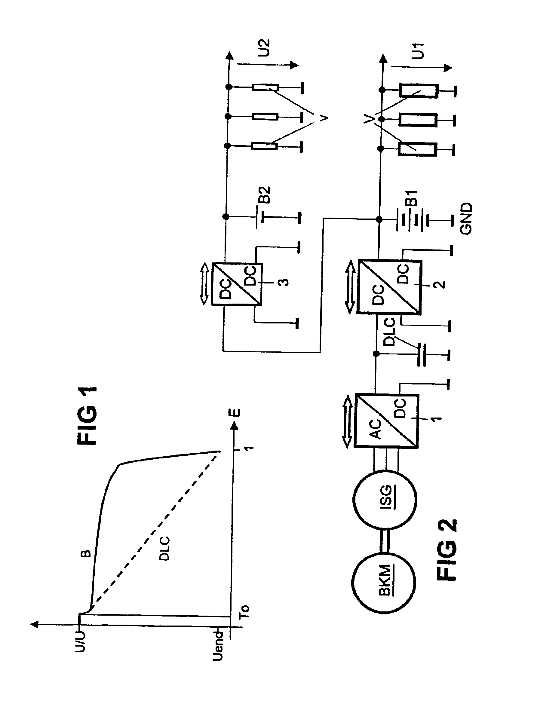
[0067]FIG. 1 shows the voltage characteristic during discharging of a double layer capacitor DLC (dashed line) and a lead-acid battery B (solid line). The difference in the voltage characteristics of the capacitor and battery from time To means that it is not possible to join the two storage mechanisms directly in a vehicle electric system. They can only be joined using an additional actuator.

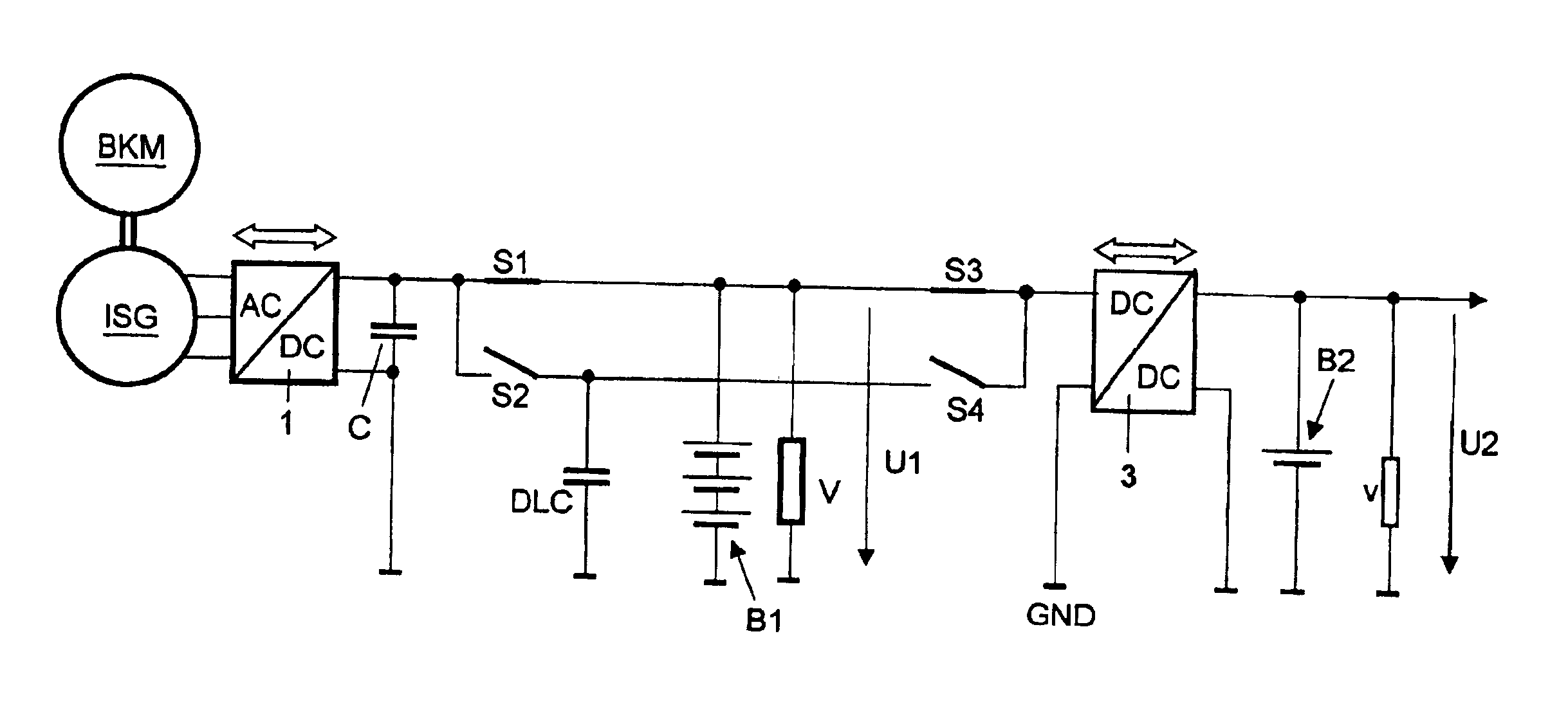
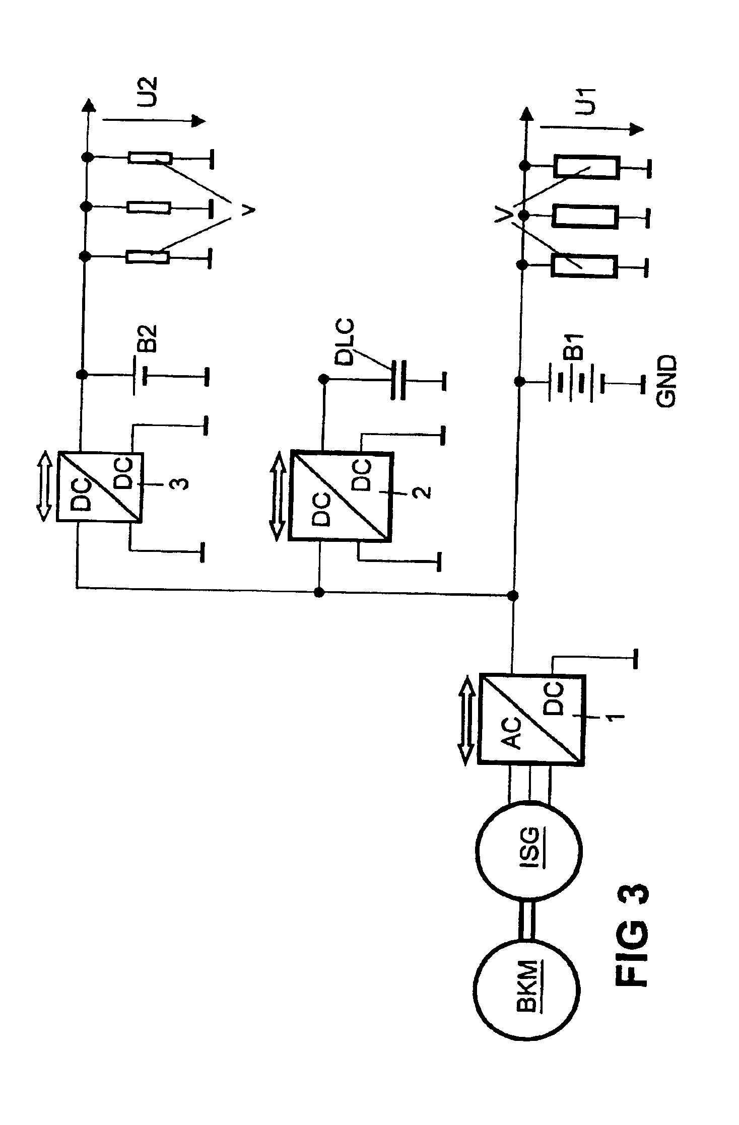
[0068]FIG. 2 shows a circuit diagram of a known 42 V / 14 V motor vehicle electric system having an integrated starter-generator ISG in which a double layer capacitor DLC is used and in which a bi-directional DC / DC converter 2 is employed as additional actuator between said double layer capacitor and a 36 V battery B1.

[0069]The operations carried out using this circuit are controlled / regulated by a control / regulation circuit (not shown).

[0070]The integrated starter-generator ISG is an asynchronous motor that is coupled mechanically to an internal combustion engine BKM and is connected to the doub...


PUM


Abstract

A starter-generator (ISG) is mechanically connected to an internal combustion engine (BKM), comprises a bi-directional AC/DC converter (1), and can be connected to an accumulator (B1) by means of a first switch (S1), and connected to a double layer capacitor (DLC) by means of a second switch (S2). The accumulator (B1) is either connected to the double layer capacitor (DLC) by means of a control circuit (PWM), or the accumulator (B1) and the double layer capacitor (DLC) are connected to a bidirectional DC/DC converter (3) and to a second accumulator (B2) by means of a third switch (S3) and a fourth switch (S4).

Description

CROSS REFERENCE TO RELATED APPLICATION[0001]This application is a continuation of copending International Application No. PCT / DE01 / 00601 filed Feb. 16, 2001 and claiming a priority date of Feb. 16, 2001, which designates the United States.TECHNICAL FIELD OF THE INVENTION[0002]The present invention relates to a motor vehicle electric system.BACKGROUND OF THE INVENTION[0003]A starter-generator in a motor vehicle can in principle be operated at a vehicle electric system voltage of 14 V (14 V or, more precisely, 14.4 V is the charging voltage of a 12 V battery). It is technically expedient in this respect to limit the power output and also the generator output to no more than 3 kW, as otherwise the vehicle electric system currents would be too high. A starter-generator can start the internal combustion engine and supply the electric loads during the journey at a vehicle electric system voltage of 14 V, but an output of more than 3 kW is required for additional functions such as boost (a...

Claims


Application Information

Patent Timeline
IPC IPC(8): H02J7/14H02J7/34H02P9/14H02P9/30B60R16/02B60R16/03F02N11/04F02N11/08H02J9/06
CPCF02N11/04F02N11/0866H02J7/1446H02J7/345H02P9/307H02J7/1423B60R16/03F02N2011/0885F02N2011/0888H02P2101/45Y02T10/7005Y02T10/7022H02J2310/46Y02T10/70B60R16/02
Inventor BOLZ, STEPHANKNORR, RAINER
Owner CONTINENTAL AUTOMOTIVE GMBH
Why Eureka
Try Eureka