
Cardiac pacemaker with adjustable stimulation interval

a technology of a pacemaker and an adjustable stimulation interval, which is applied in the field of cardiac pacemakers, can solve the problems of stim-t interval dependence, shortening to a considerable degree, and not shortening, and achieves the effect of quick and accurate regulation and avoiding overload by too high stimulation frequency

Inactive Publication Date: 2005-07-19
ST JUDE MEDICAL
View PDF7 Cites 9 Cited by
  • Summary
  • Abstract
  • Description
  • Claims
  • Application Information

AI Technical Summary

Benefits of technology

[0014]An object of the invention is to provide a cardiac pacemaker which renders possible quick and accurate regulation of the stimulation frequency or respectively of the duration of the stimulation interval, and overloading by too high a stimulation frequency is avoided.
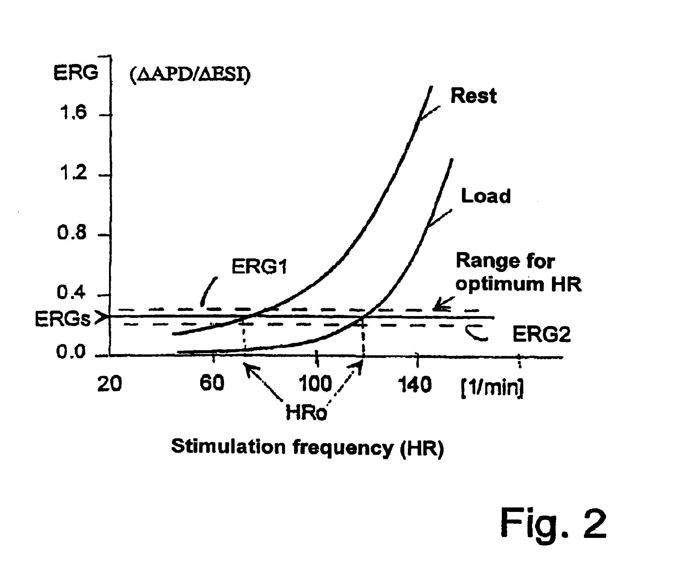
[0016]The cardiac pacemaker according to the invention which has an individually optimized regulation of the duration of the stimulation interval, avoids the necessity of determining a BV- or HTV-dependent measuring parameter and makes possible, through evaluation of the electric restitution or of the gradient of the electric restitution with the aid of the standard detection of the endocardiac ECG, a regulation of the stimulation frequency or of the duration of the stimulation interval by means of a function parameter of the heart, which directly reproduces the stress state of the patient, changes in the capacity of the myocardium and acute worsening of myocardial performance being taken into account in the frequency adaptation. Here the modulation of individual stimulation intervals is carried out in such a way that the average adjusted interval duration does not change.
[0022]The control system according to the invention using a single pulse modulation and detection of the electric restitution causes a quick and accurate regulation of the stimulation frequency, since the electric restitution is controlled mainly by a quick reaction mechanism controlled by neurons.

Problems solved by technology

The principle disadvantage of a frequency control system of this kind is due to the fact that the stim-T interval does not shorten only with an increase in stress, but shortens to a considerably greater degree through the rise of the stimulation frequency itself.
A further disadvantage of this system of frequency control is the fact that the measured stim-T intervals are dependent on hormonal secretions, i.e., they respond to hormones secreted by the adrenal cortex and transported via the blood circulation.
This method depends on the stability and the accuracy of the s02 sensor catheter, which in practice have not proved to be sufficient, and the method has the disadvantage that on account of the necessary long change periods it is not possible in the necessary time of a few minutes to differentiate whether the measured s02 change is caused by the frequency change or by other influencing variables.
This method has the disadvantage that the principle of modulating individual stimulation intervals here is only used as a filtering and calibration method, i.e. as an interim step to determine the beat volume and thus the heart time volume (HTV).
The determination of the beat volume, despite an improvement in the signal-to-noise-ratio as a result of the individual pulse modulation, has in practice still proved too inaccurate to be able to carry out reliable hemodynamic optimization.
This means that optimization of the stimulation by controlling the heart time volume has in practice been problematic, since either the specific sensor catheters for measuring the beat volume or the HTV-dependent measuring parameters still have no adequate long-term stability, or measurements of the beat volume using standard catheters via the impedance are not sufficiently reliable.
Moreover the evaluation becomes very complex since the mechanical transmission functions also detected and which falsify the measuring result must also be taken into account.

Method used


Image

  • Cardiac pacemaker with adjustable stimulation interval
  • Cardiac pacemaker with adjustable stimulation interval
  • Cardiac pacemaker with adjustable stimulation interval

Examples


Embodiment Construction

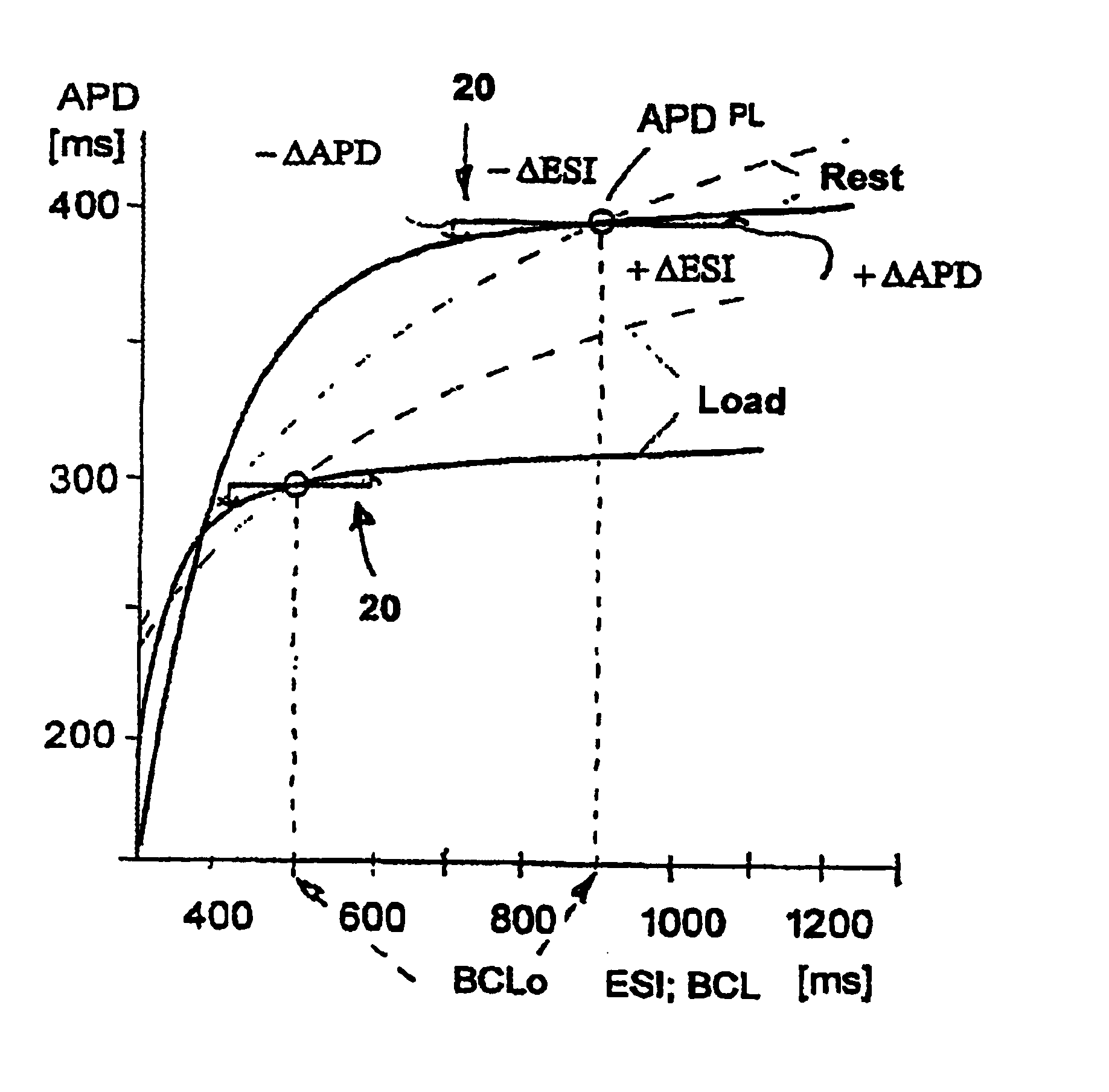
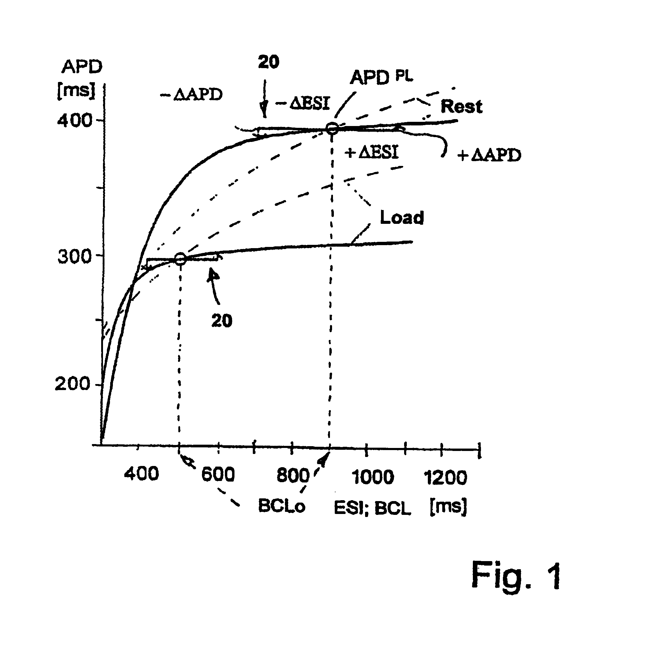
[0027]The dependence of the duration of,the action potential AP of the myocardium as a function parameter of the duration of the diastole td is designated as electric restitution. If this is spontaneously changed during a single heart cycle, for example through an extrasystole, then the action potential or its duration changes. The duration of the action potential is defined by the interval between the beginning of the stimulation and the time at which the action potential has sunk by 90%, and it decreases if the time interval between two successive stimulation pulses becomes smaller. Here a distinction is to be made between the APD change after an extrasystolic stimulation interval and the APD change after a change in the average or basic heart frequency (HR =1 BCL) according to prior art.

[0028]This alteration behavior after an extrasystolic stimulation interval can be described by a double exponential function which is referred to as the electric restitution curve ER.

[0029]The ele...


PUM


Abstract

A cardiac pacemaker has a pulse generator which emits stimulation pulses which are respectively separated by stimulation intervals and which collectively have an average duration. A modulation device alternatingly shortens and lengthens the stimulation intervals, without changing the average duration. An evaluation unit analyzes signals detected after each stimulation pulse and determines the electric restitution of the heart at the average stimulation interval duration on the basis of a measurement of the duration of the action potential. Changes in a measuring variable, associated with the duration of the action potential, caused by the modulation of the stimulation intervals is determined in a relationship to the average duration of the stimulation interval. This relationship is compared with at least one predetermined value, and the average duration of the stimulation interval is controlled on the basis of this comparison.

Description

BACKGROUND OF THE INVENTION[0001]1. Field of the Invention[0002]The present invention is directed to a cardiac pacemaker, and in particular to a cardiac pacemaker wherein the stimulation interval between stimulation pulses is adjustable.[0003]2. Description of the Prior Art[0004]A generally known cardiac pacemaker is the so-called QT-or stimulus-T pacemaker such as is described for example in U.S. Pat. No. 4,228,803. Such a pacemaker has means with which the median stimulation frequency can be adapted to changes in physical and psychic stress.[0005]To this end a circuit is provided which evaluates the ECG signal derived intracardially, detecting the beginning or the maximum of the T wave. Since the time interval between stimulation and the start of the T wave, the so-called stim-T interval shortens with increasing stress, the circuit delivers a physiological measuring parameter with which the stimulation frequency can be adapted to changing stresses.[0006]The principle disadvantage ...

Claims


Application Information

Patent Timeline
IPC IPC(8): A61N1/365
CPCA61N1/365
Inventor HEINZE, ROLANDSTANGL, KARL
Owner ST JUDE MEDICAL
Learn More