
Concentric tilted double-helix dipoles and higher-order multipole magnets

a technology of multi-pole magnets and dipoles, applied in the field of concentrated tilted double-helix dipoles and higher-order multi-pole magnets, can solve the problems that none of the patent references provides solutions to all the drawbacks of conventional prior art systems described above, and achieves the effect of convenient, less expensive, and improved performan

Inactive Publication Date: 2005-07-26
GOODZEIT CARL L +2
View PDF12 Cites 143 Cited by
  • Summary
  • Abstract
  • Description
  • Claims
  • Application Information

AI Technical Summary

Benefits of technology

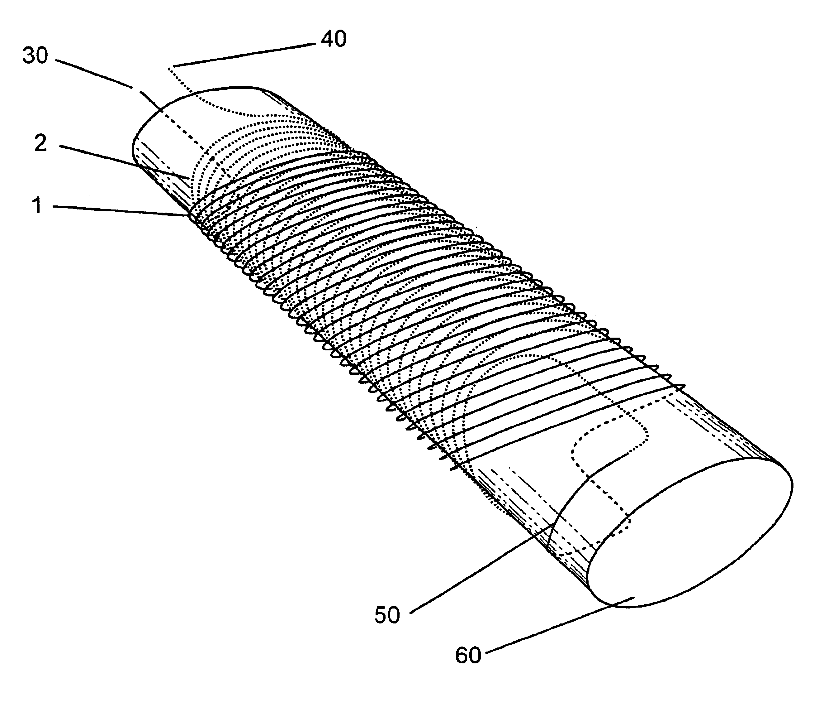
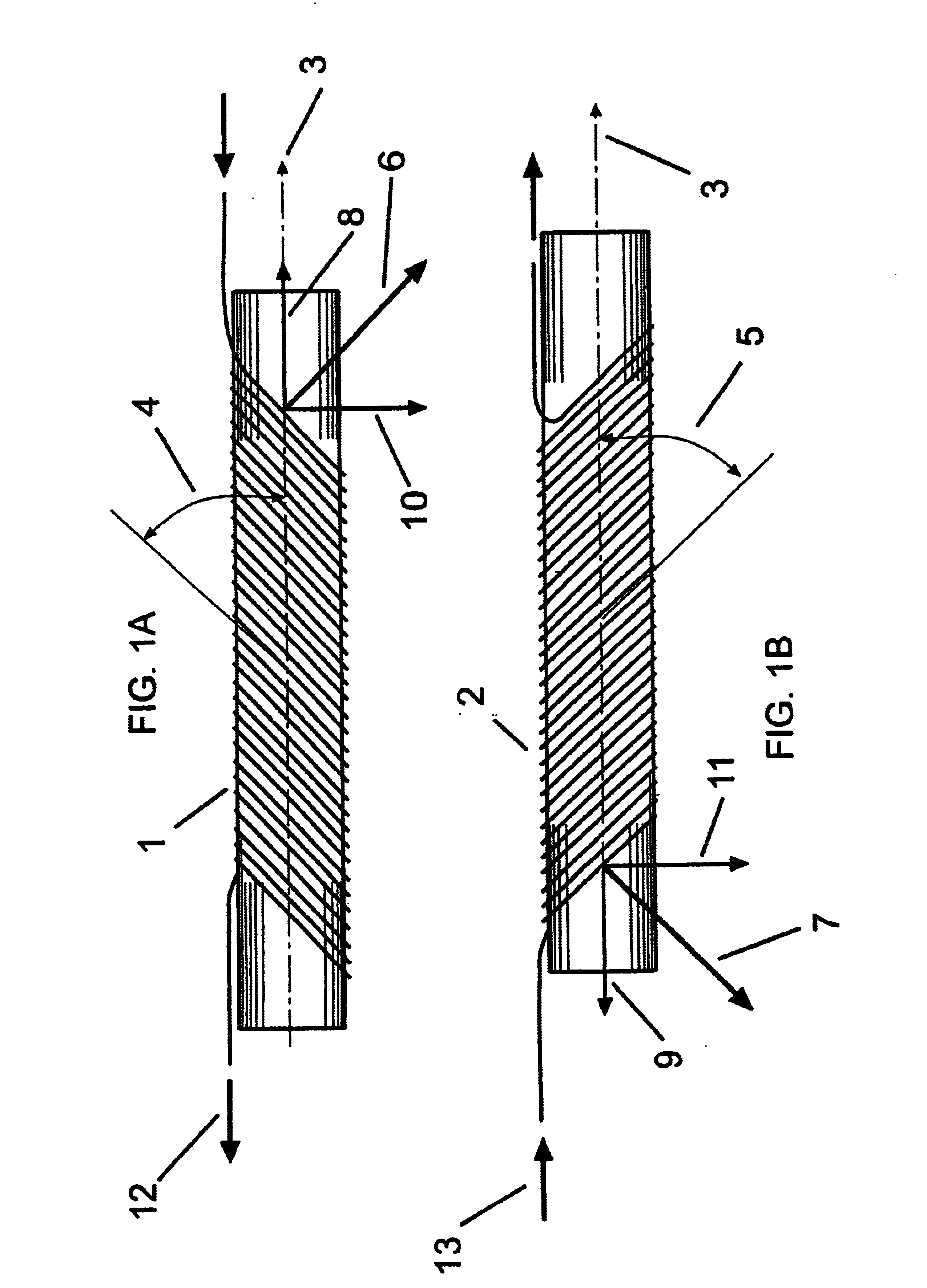
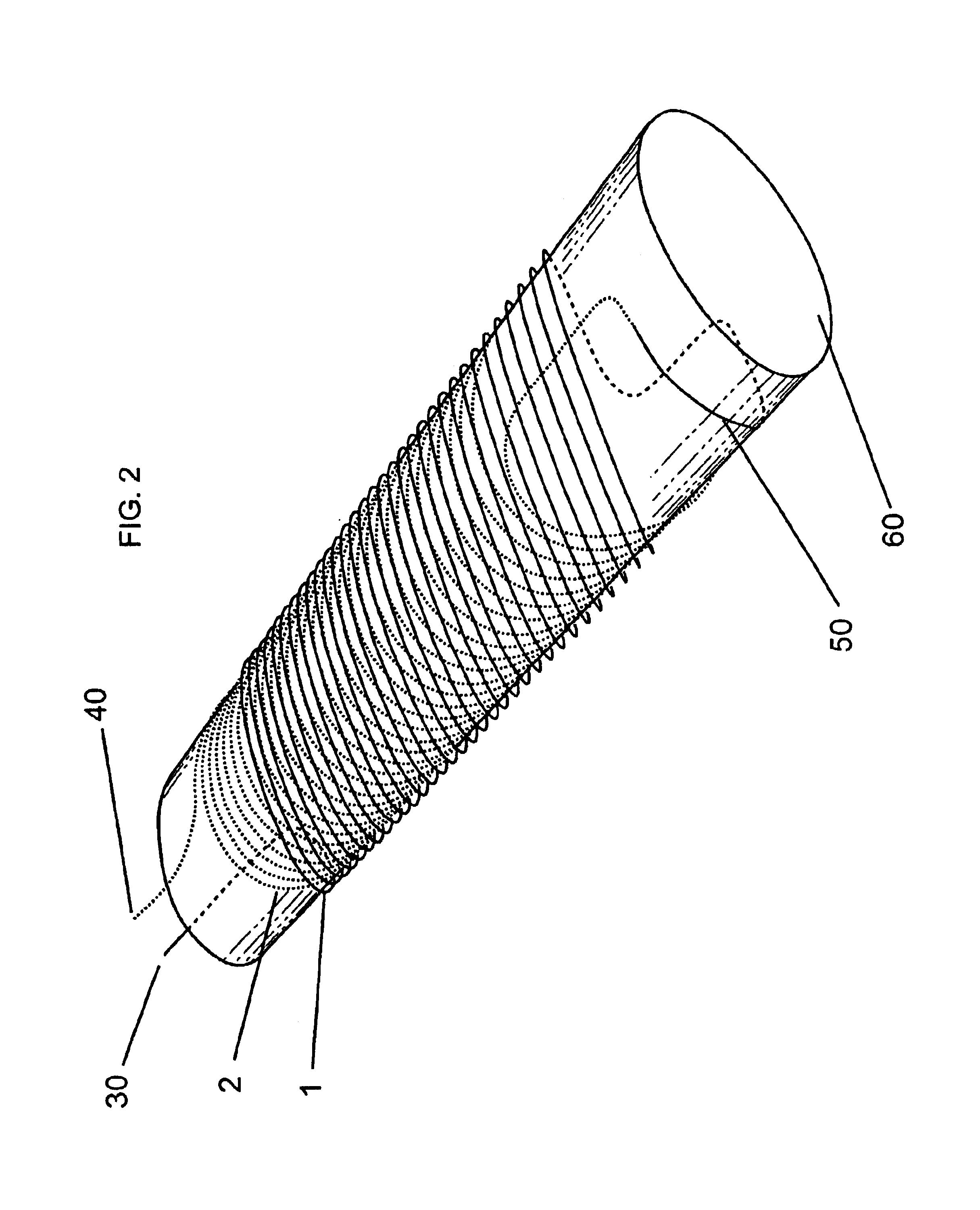
[0021]A primary objective of the invention is to provide an easy, and thus less costly, method to manufacture dipole magnets suitable for accelerators and other dipole applications mentioned. The tilted double-helix coil configuration effectively eliminates numerous and expensive parts that are used to provide precise conductor positioning in the construction of the coils of conventional superconducting accelerator magnets such as conventional racetrack and block coil dipole magnets.
[0022]A secondary objective of the invention is to provide a dipole magnet configuration that eliminates the need for applying a high level of azimuthal pre-stress that is required for racetrack, saddle shaped or current shell approaches to dipole magnet design. The invention configuration simplifies the necessary technology, and thus eliminates the equipment and design complications associated with that activity.
[0023]A third objective of the invention is to provide a method of manufacturing a dipole magnet that eliminates the need for special end parts normally used in racetrack accelerator coils. Since a coil layer of a double-helix magnet is made by a continuous helical wind with the same sized loop, the method of manufacture is greatly simplified, and the geometry of the ends of the double-helix magnets is the same as in the body of the magnet.

Problems solved by technology

None of the patent references provide solutions to all the drawbacks of conventional prior art systems described above.

Method used


Image

  • Concentric tilted double-helix dipoles and higher-order multipole magnets
  • Concentric tilted double-helix dipoles and higher-order multipole magnets
  • Concentric tilted double-helix dipoles and higher-order multipole magnets

Examples


case 1

, Circular Aperture Coil

[0070]The specific case of a coil with a circular aperture in the x-y plane is obtained with the dimensions of the aperture being b=a; hence e=1, r=a, and the coordinates of the conductor path, including the advance of the helix with angle, cθ, are:[0071]x=a cos θ[0072]y=a sin θz=c⁢ ⁢θ+a⁢ ⁢sin⁢ ⁢θtan⁢ ⁢α

When this is the case, the CoilCad™ calculations show that systematic field errors of double-helix dipoles are on the level of 10−8 or less relative to the main dipole field.

case 2

ical Aperture Coil

[0073]Numerical calculations by CoilCad™ show that field errors on the level of 10−8 or less relative to the main dipole field also occur for an elliptical aperture double-helix dipole coil when the tilted ellipse of the conductor path, 82, is a circle. That is the case when the aperture dimensions are such that a=b′=b / sin α. Thus e≡ab=1sin⁢ ⁢α

and the descriptive geometry for such a coil is[0074]x=r cos θ[0075]y=r sin θz=c⁢ ⁢θ+r⁢ ⁢sin⁢ ⁢θtan⁢ ⁢α

where r=a⁢ ⁢sin⁢ ⁢αsin2⁢θ+sin2⁢α⁢ ⁢cos2⁢θ

Thus, for each tilt angle α, there is an optimal ellipse geometry that will give a circular conductor path in the tilted plane and thus produce an error free dipole field.

[0076]In summary, it has been shown with numerical calculations using the precise 3 dimensional winding pattern of double-helix dipoles that all higher-order field multipoles essentially vanish in each individual tilted coil for the 2 cases discussed above. A small, skew dipole component caused by the helical solenoi...


PUM

PropertyMeasurementUnit
Magnetic fieldaaaaaaaaaa
Poweraaaaaaaaaa

Abstract

Concentric tilted double-helix magnets, which embody a simplified design and construction method for production of magnets with very pure field content, are disclosed. The disclosed embodiment of the concentric tilted double-helix dipole magnet has the field quality required for use in accelerator beam steering applications, i.e., higher-order multipoles are reduced to a negligibly small level. Magnets with higher multipole fields can be obtained by using a simple modification of the coil winding procedure. The double-helix coil design is well-suited for winding with superconducting cable or cable-in-conduit conductors and thus is useful for applications that require fields in excess of 2 T. The coil configuration has significant advantages over conventional racetrack coils for accelerators, electrical machinery, and magneto-hydrodynamic thrusting devices.

Description

[0001]This invention relates to dipole and higher multipole magnets, and in particular to concentric tilted double-helix dipole magnets, for applications in particle beam steering, magneto-hydrodynamic thrusting, and stators and rotors in electrical machinery, and this invention would be particularly important for applications that require use of superconductors, but could also be used with normal conductors, and this invention claims the benefit of priority to U.S. Provisional Application 60,324,415 filed Sep. 24, 2001.BACKGROUND AND PRIOR ART[0002]It is well known that dipole magnets can be used for particle beam steering in charged particle accelerators, beam lines, and storage rings. Dipole magnets have also been used in magneto-hydrodynamic thrusting devices, for applications such as propulsion of sea going vessels or fluid pumping, and for magneto-hydrodynamic power generation. Additional applications for these magnets have included electrical machinery such as motors and gene...

Claims


Application Information

Patent Timeline
IPC IPC(8): H01F7/20H01F41/04H01F6/06H01F41/06H01F6/00H05H7/04
CPCH01F7/202H01F41/048H02K3/04H02K15/0464H02K55/00H02K55/04H05H7/04H01F6/00H01F6/06H01F41/0633Y02E40/625Y02E40/62H01F41/082Y02E40/60
Inventor GOODZEIT, CARL L.MEINKE, RAINER B.BALL, MILLICENT
Owner GOODZEIT CARL L
Learn More