Bleed valve system

a bleed valve and valve body technology, applied in the field of industrial machinery, can solve the problems of compressor and/or engine failure, compressor and/or engine stall, and not allowed to achieve the ideal balance between smooth vibration and engine efficiency, and achieve the effect of optimizing operation, facilitating operation, and adjustment during operation

Inactive Publication Date: 2005-07-26
JOHNSON DAVID L
View PDF1 Cites 27 Cited by
  • Summary
  • Abstract
  • Description
  • Claims
  • Application Information

AI Technical Summary

Benefits of technology

[0022]The present invention provides a system that enables or facilitates operation (and adjustment during operation) of gas turbine engine bleed valves via the interrelationship between the components of the system and a programmable logic device. In particular, the system of the present invention optimizes the operation (i.e., the opening and closing) of bleed valves by utilizing a control device (e.g., a programmable logic device), which sends signals to open or close the bleed valves based on electronically measured / sensed pressure values within a gas turbine engine. As such, the system of the present invention differs from conventional systems, which utilize mechanical means to control how and when bleed valves open and close.

Problems solved by technology

There are several problems with conventional rotary gas turbine engines—especially twin axial compressor type engines—that arise during the acceleration and deceleration of the engine, most notably a mechanical lag / delay between the high and low turbine sections that are being driven by the expanding combustion gases.
This momentum delay causes the high- and low-pressure compressors to turn at different rates, and that, in turn, has the effect of trapping unused compressed air between the low- and high-pressure compressors.
This trapped air condition—if unalleviated—will partially or completely halt the rotation of the compressor blades, thus causing the engine to undergo “compressor stall.” Compressor stall, in turn, causes associated engine vibration, which, if recurrent, will ultimately lead to compressor and / or engine failure.
However, although conventional gas turbine engine bleed valve systems have proven effective to at least somewhat smooth the vibration of gas turbine engines, the timing of the opening and closing of the various bleed valves has not allowed for an ideal balance between smooth vibration and engine efficiency.
Specifically, whereas flight jet engines are operated primarily at altitudes thousands of feet above sea level, where the air is both dry and clean (and, thus, compressible), gas turbine engines are operated at or below sea level, where the air is generally unclean and moisture-laden (and, thus, incompressible).
Over time, circulation of moisture-laden, incompressible air through a gas turbine engine compressor and into a series of bleed valves will result in degradation of the bleed valves, which, in turn, will either require costly repair of the bleed valves, or, if unnoticed, will cause premature valve failure.
In a similar vein, the dirt and moisture contained in the air can cause friction, which, in turn, can necessitate costly repair, or lead to failure of the springs, shims and / or spacers that comprise the pressure actuators and enable them to function properly.

Method used


Image

  • Bleed valve system
  • Bleed valve system
  • Bleed valve system

Examples


Embodiment Construction

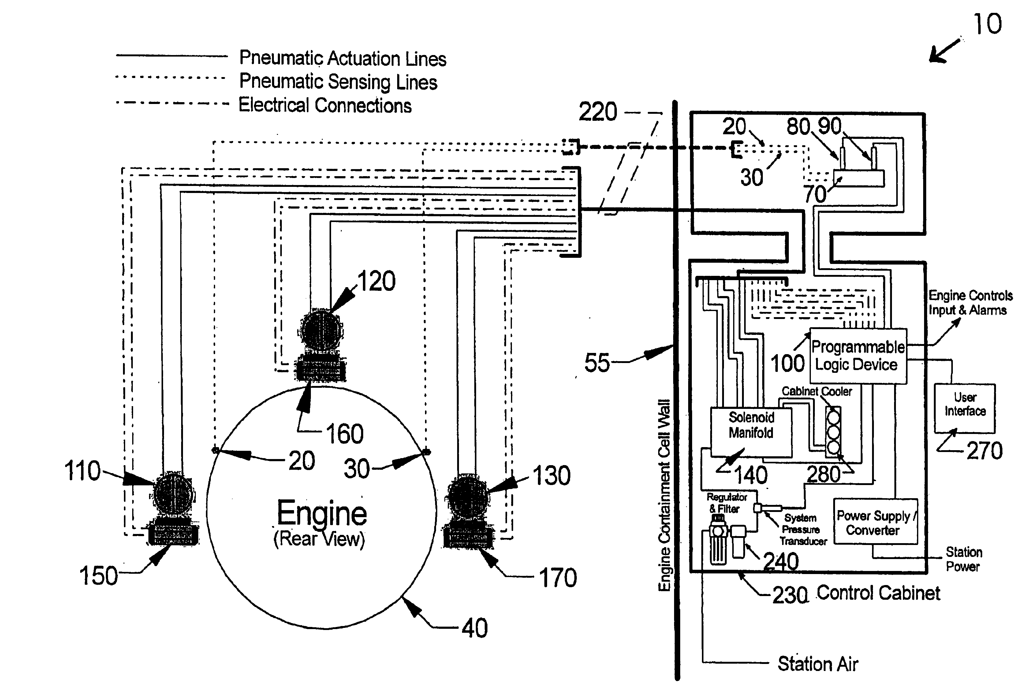
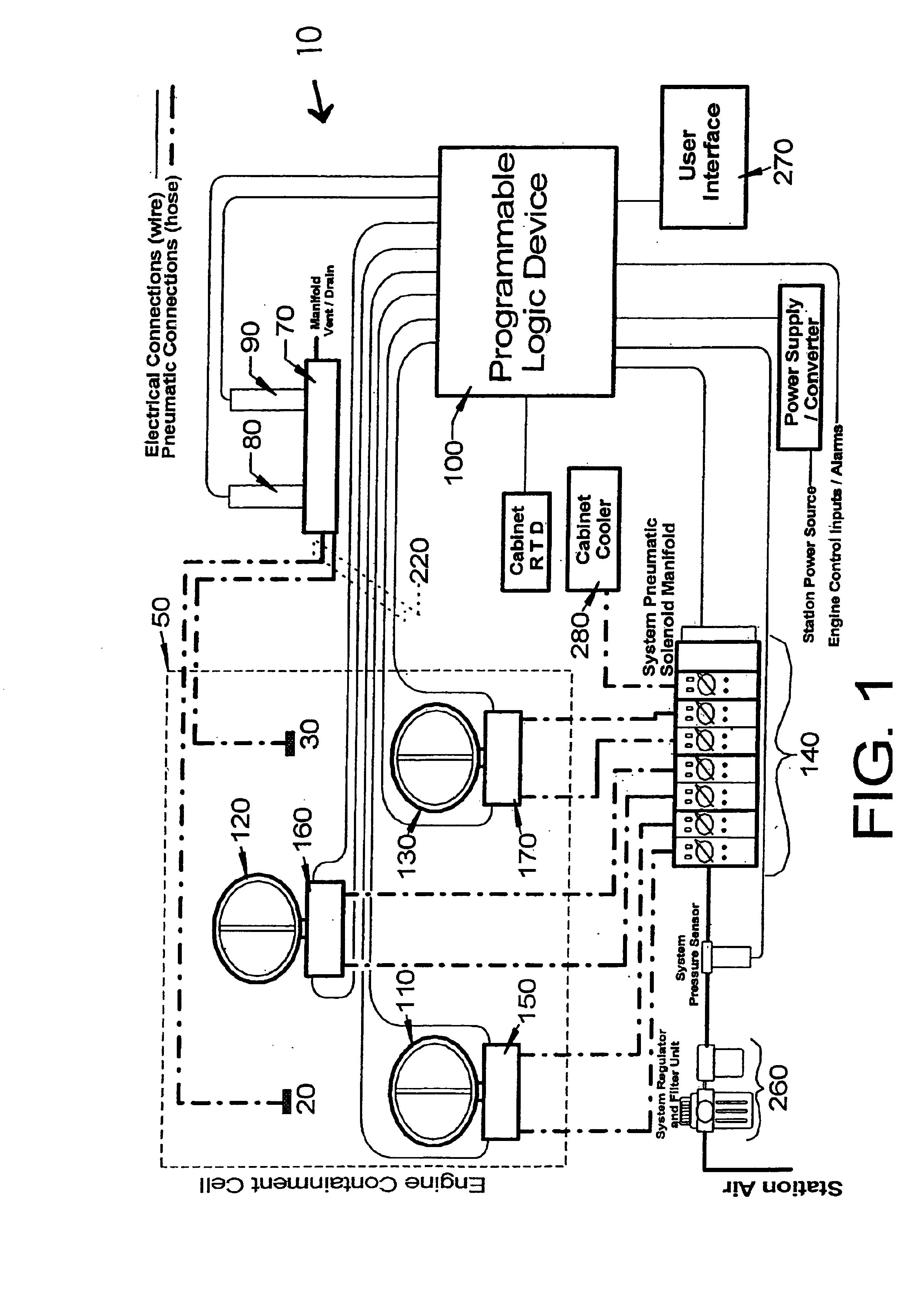
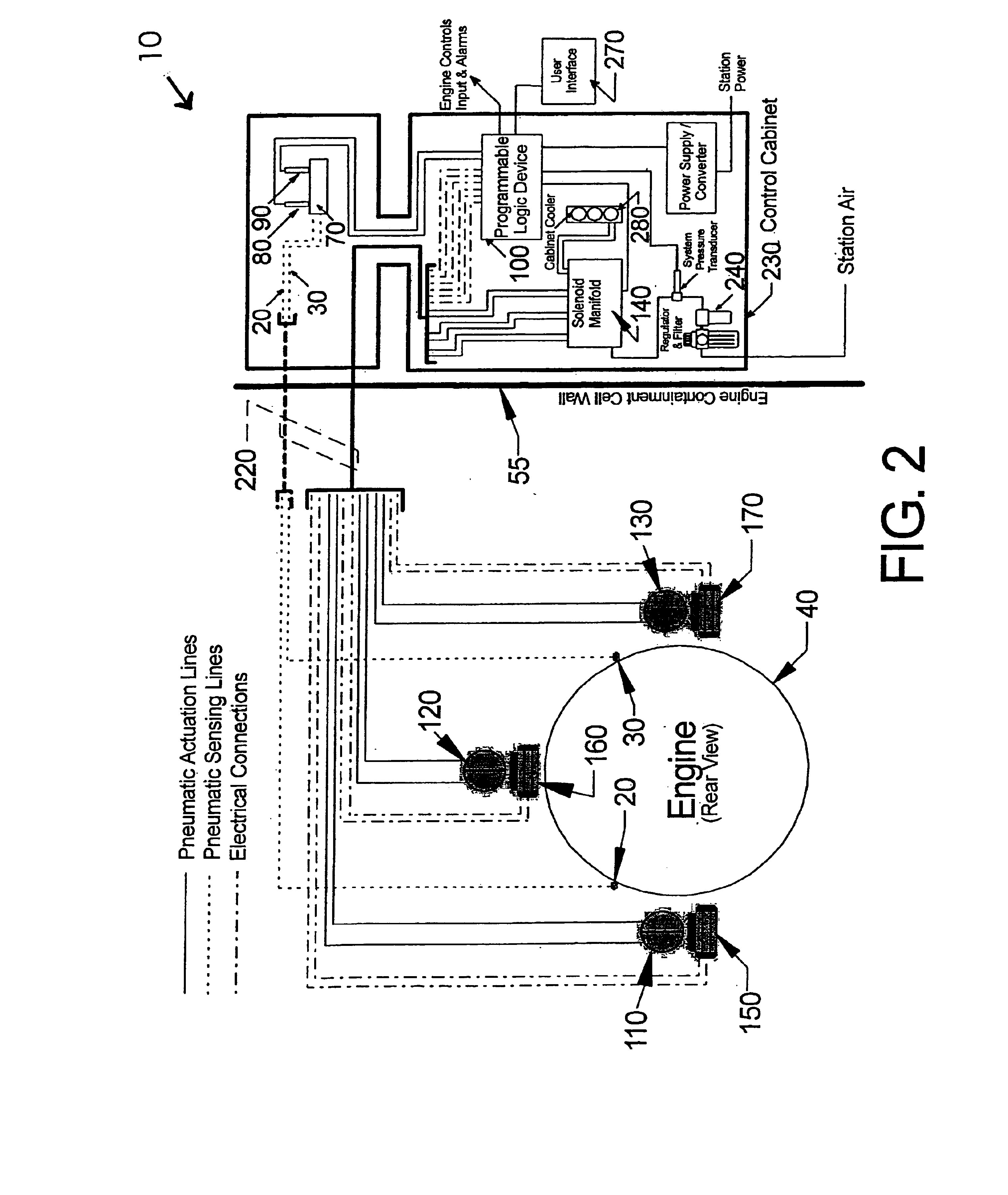
[0049]The present invention provides a system that enables or facilitates operation (and adjustment during operation) of gas turbine engine bleed valves via the interrelationship between the components of the system and a programmable logic device.

[0050]In particular, the system 10 (see FIGS. 1 and 2) of the present invention optimizes the operation (i.e., the opening and closing) of bleed valves by utilizing a programmable logic device, which sends signals to open or close the bleed valves based on electronically measured / sensed pressure values within a gas turbine engine. As such, the system 10 of the present invention differs from conventional systems, which utilize mechanical means to control how and when bleed valves open and close.

[0051]The pressure of the engine is sensed by the programmable logic device due to the interrelationship of several components of the system. As shown in FIG. 1 and, in particular, FIG. 2, a plurality of pressure sensing lines 20, 30 are in communica...


PUM


Abstract

Disclosed is a system for operating gas turbine engine bleed valves in response to pressure values within the engine, wherein the engine pressure values are sensed electronically and routed to a programmable logic device, and wherein the programmable logic device control the opening and closing of the bleed valves in a manner that allows for reduced engine vibration with minimal loss of engine efficiency.

Description

CROSS REFERENCE TO RELATED APPLICATION[0001]This application claims priority from, and incorporates by reference the entirety of U.S. Provisional Patent Application Ser. No. 60 / 336,619, which was filed on Dec. 4, 2001.BACKGROUND OF THE INVENTION[0002]1. Field of the Invention[0003]The present invention relates to industrial machinery, and, in particular, to industrial gas turbines and operation thereof. More particularly, the present invention provides a sys tem for electronically controlling the operation of gas turbine engine bleed valves.[0004]2. Description of Related Art[0005]Gas turbines serve a variety of important purposes (e.g., generating electricity; pumping oil; compressing natural gas, turning a ship's propeller), and operate by converting thrust power into shaft or rotary power to turn or “drive” one or more pieces of industrial machinery.[0006]The engine of a gas turbine is a rotary or axial type engine that spins around a common shaft located in the center of the eng...

Claims


Application Information

Patent Timeline
Patent Type & Authority Patents(United States)
IPC IPC(8): F01D17/08F01D17/00F02C9/00F02C9/18F16K31/16F16K31/163
CPCF01D17/08F02C9/18F16K31/1635F05D2270/54F05D2270/301F05D2270/66F04D27/0223
Inventor JOHNSON, DAVID L.
Owner JOHNSON DAVID L
Why Eureka
Try Eureka