Control of items in a complex system by using fluid models and solving continuous linear programs

a fluid model and complex system technology, applied in the field of system control, can solve problems such as inability to find optimal solutions, inability to find optimal controls, and inability to solve optimal solutions

Inactive Publication Date: 2005-07-26
WEISS GIDEON
View PDF18 Cites 14 Cited by
  • Summary
  • Abstract
  • Description
  • Claims
  • Application Information

AI Technical Summary

Benefits of technology

[0020]Accordingly, several objects and advantages of my invention are:
[0021]It provides a general unified method for the control of systems as described above, which models the system as a whole, and which optimizes the whole system.
[0022]It provides a method which takes the middle way between the approach of finite horizon discrete optimization and of steady state stochastic optimization, by optimizing the system over a finite time horizon, and using only on-line decision rules, where such on line decision rules use the state of the system at the decision moment, but do not require detailed information for the whole ...

Problems solved by technology

Methods used to control such systems are mostly of two kinds: Some are concerned with local optimization of a small part of the system, others, which view the whole system are ad-hoc methods, which are unable to find optimal solutions.
This method is slow, cumbersome, and expensive.
However, owing to the complexity of said systems, this method cannot find optimal controls.
Both approaches are often inadequate to handle problems of the size that arises in practice.
Furthermore, each approach has a grave conceptual fault: In a finite horizon detailed discrete optimization one needs to use precise data for the entire time horizon, whereas in reality only data of the current state is accurate.
As a result the quality of the derived controls degrades with time.
However, research to date has failed to produce efficient algorithms for the solution of CLP and SCLP problems.
The m...

Method used


Image

  • Control of items in a complex system by using fluid models and solving continuous linear programs
  • Control of items in a complex system by using fluid models and solving continuous linear programs
  • Control of items in a complex system by using fluid models and solving continuous linear programs

Examples


first embodiment

[0082]the fluid modeling stage of our methods and apparatus includes the case when the real system is a manufacturing system. The manufacturing system comprises:[0083]A plurality of machines i=1, . . . , I which are the resources.[0084]A plurality of processing steps, numbered j=1, . . . , J which are the actions.[0085]A plurality of partially manufactured parts which are the items, and each part in process can be classified according to its stage of completion, where stages of completion in the manufacturing process are numbered as k=1, . . . , K.[0086]A particular processing step j is always applied to items in a particular stage of completion k=k(j), and it uses a particular machine i=i(j), for a duration with an average mj. The result of the application of processing step j to a part in stage of completion k(j) is that the stage of completion of the part changes. A fraction Pj,l of the parts in stage of completion k(j) will change their stage of completion to l by the applicatio...

second embodiment

[0093]the fluid modeling stage of our methods and apparatus includes the case when the real system is a city wide traffic system, with centralized control of traffic signals, and with some control over the routing of individual cars by means of signalling and communications with car operators. The traffic system comprises:[0094]A plurality of road sections and a plurality of intersections connecting the road sections[0095]A plurality of vehicles, classified by their locations on road sections, and by their destinations

[0096]The fluid buffer levels xkl(t) approximate the number of vehicles on road section k with destination l at time t. Controls ukR(t), ukD(t), ukL(t) indicate the rate at which vehicles on road section k are directed through intersection to the right, directly ahead, and to the left, respectively. Capacity constraints limit the sum ukR(t)+ukD(t)+ukL(t), and express the allocation of fractions of the time to different directions in the traffic signals.

1.3 Fluid Modeli...

third embodiment

[0097]the fluid modeling stage of our methods and apparatus includes the case when the real system is a communication system, as embodied in a telephone system or in a internet system. The communication system comprises:[0098]A communication network comprising nodes and links.[0099]Messages, data packets, and files in transit in the system, classified by their route, where a route comprises origin node and destination node, and links along the route.

[0100]Fluid buffer levels xk(t) express total level of messages on route k. Flow rates uk express transmission rate on route k. Resource consumption of flow on route k includes all the links on this route.

1.4 Fluid Modeling of Multi-Project Scheduling


PUM


Abstract

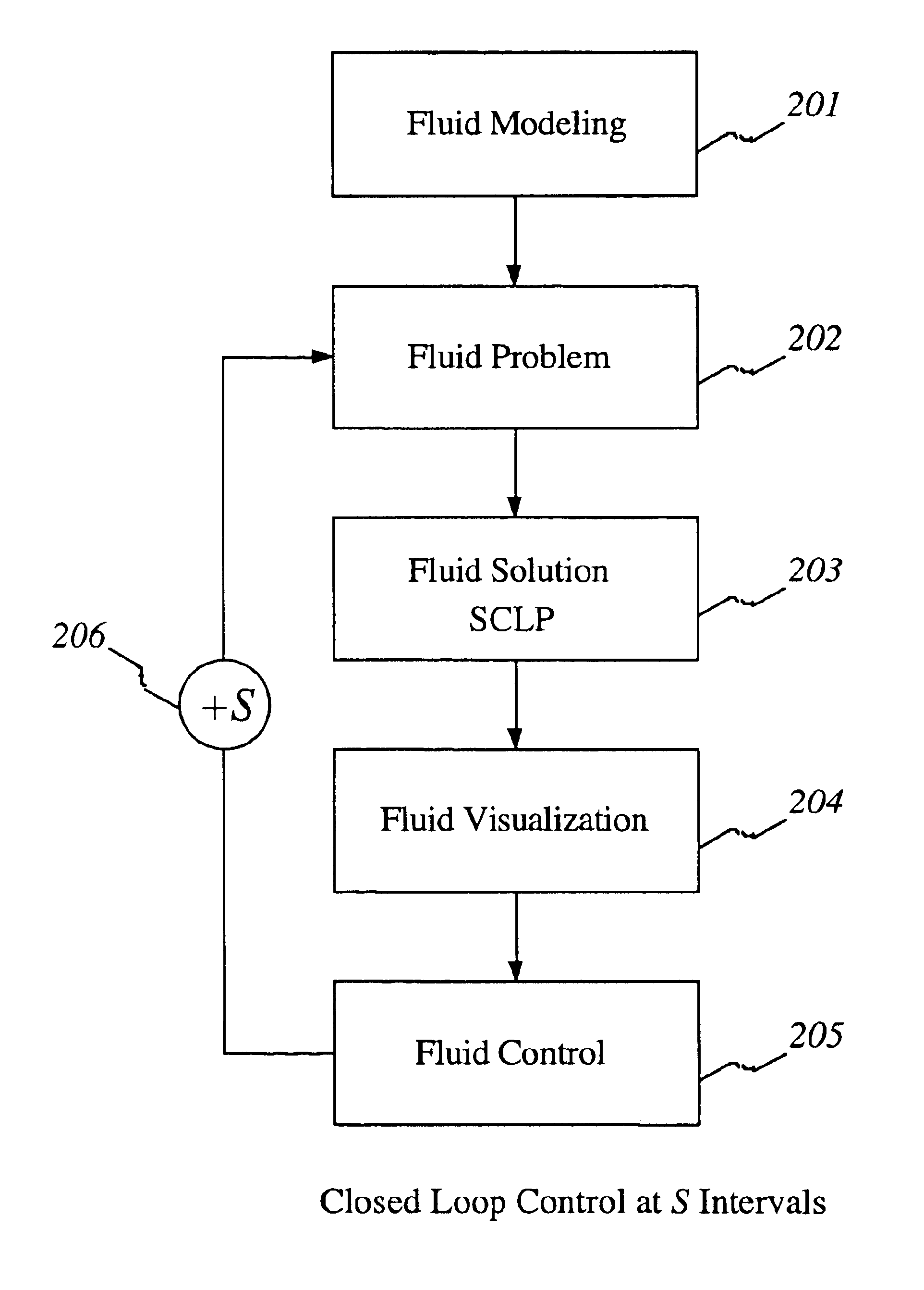
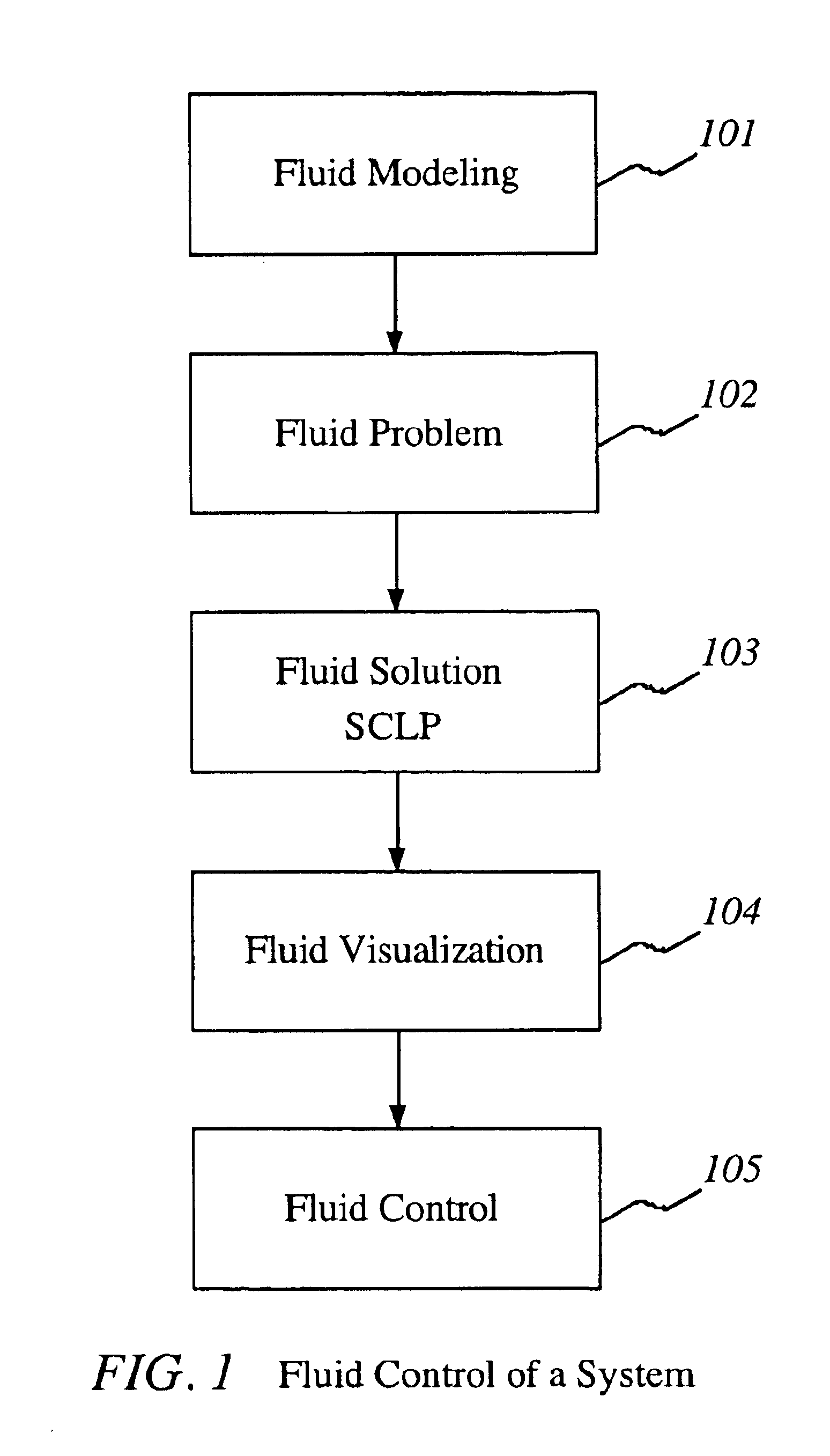
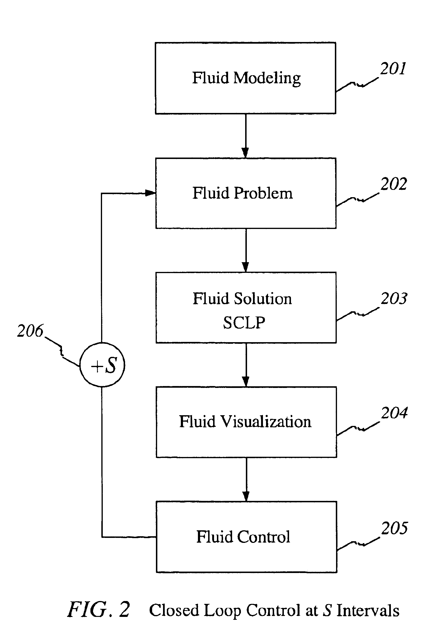
A method and apparatus for the control of a system comprising of a plurality of items through the scheduling of actions and the allocation of resources is disclosed. Primary areas of utility include manufacturing systems, city wide vehicle traffic control, multiple project scheduling, communications networks and economic systems. The method and apparatus comprise modeling the parts in such a system as fluid, formulating the control problem as a continuous linear program, using a novel algorithm to solve it, displaying the fluid solution in a meaningful way, and using the fluid solution in the control of the system.

Description

CROSS REFERENCE TO RELATED APPLICATION[0001]This application is entitled to the benefit of Provisional Patent Application No. 60 / 309,782, Filed 2001, Aug. 6.SEQUENCE LISTING OR PROGRAM[0002]This aplication contains a computer program to run a novel algorithm, on a CD.TECHNICAL FIELD[0003]This invention relates generally to the field of operations research and systems engineering and more particularly to the control of a system comprising of a large number of items by scheduling the allocation of resources to said items.BACKGROUND OF THE INVENTION[0004]The need to control systems comprising many items, where each item requires scheduling of actions and allocation of resources over time, arises in a variety of technological, industrial, and economic areas.[0005]In a manufacturing plant production of parts requires the scheduling of operations by the allocation of machines.[0006]In a city traffic system, vehicles require the use of roads and intersections to proceed from source to dest...

Claims


Application Information

Patent Timeline
IPC IPC(8): G05B17/00G05B17/02
CPCG05B17/02
Inventor WEISS, GIDEON
Owner WEISS GIDEON
Why Eureka
Try Eureka