Passive thermal control system

Inactive Publication Date: 2005-08-02
LOCKHEED MARTIN CORP
View PDF24 Cites 24 Cited by
  • Summary
  • Abstract
  • Description
  • Claims
  • Application Information

AI Technical Summary

Benefits of technology

[0015]In accordance with another aspect of the present invention, an integrated cell unit is provided. As noted above, the ability to adequately control operating temperature ranges using passive elements facilitates the deployment of integrated cell units that include a powered component together with a power generation system and a heat dissipation system. In this regard, an integrated antenna and solar array in accordance with this aspect of the invention includes: a solar array assembly having an external surface for receiving solar radiation; an antenna assembly having an external surface operative to radiate thermal energy therefrom, where the antenna external surface faces substantially opposite the array external surface. The solar array assembly is in thermal contact with the antenna assembly primarily via radiation with minimum conduction so that thermal energy passes from the solar array asse

Problems solved by technology

However, such batteries require a narrow operating temperature range for optimal performance, for example, an operating range between about +30° C. and −15° C. Such batteries typically also require limited depth of discharge and careful charge control to more fully realize their potential benefits for spacecraft applications.
In the spacecraft environment, a number of obstacles complicate passive thermal control.
First, there are typically tremendous and greatly varying thermal dissipation requirements.
The magnitude of such heat dissipation may be the result of, for example, the operation of many components in a small volume and high solar fluxes on radiation attenuating surfaces.
Accordingly, one challen

Method used


Image

  • Passive thermal control system
  • Passive thermal control system
  • Passive thermal control system

Examples


Embodiment Construction

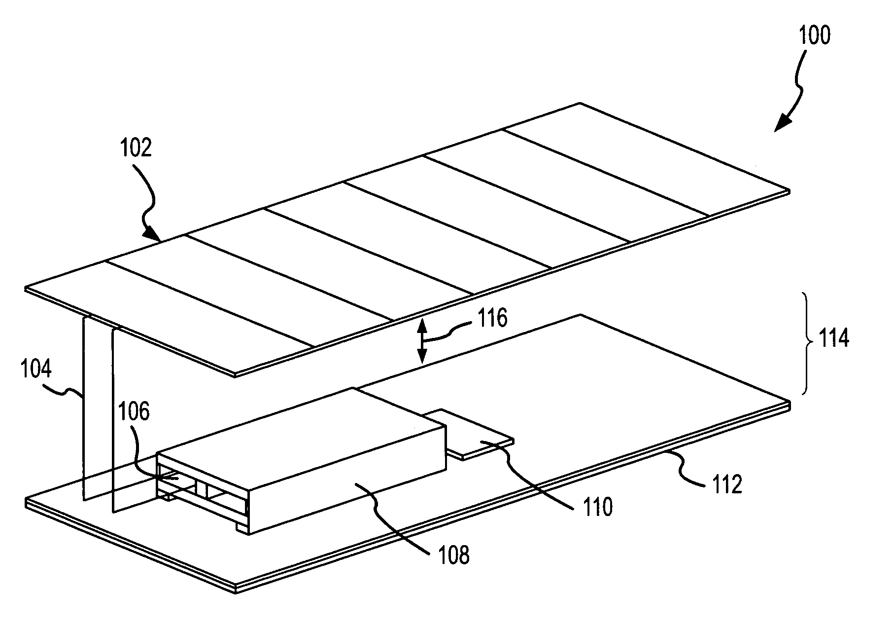
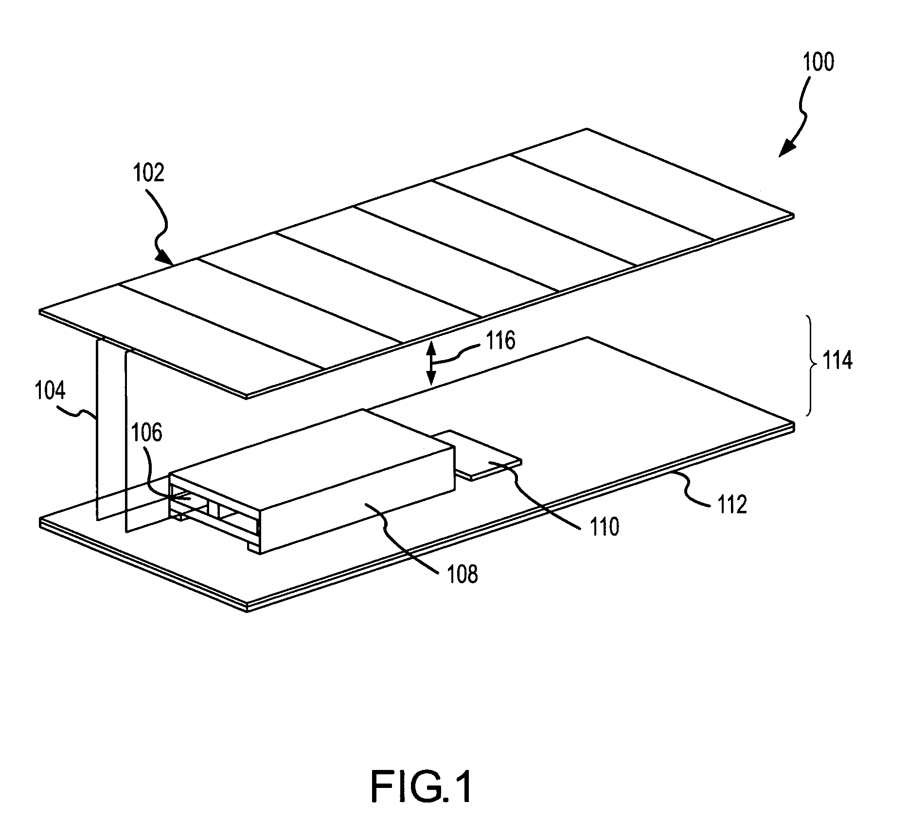
[0024]The present invention is directed to a passive thermal control unit and associated systems and methodology relating to thermal dissipaters associated with equipment requiring a narrow temperature range in which to function. In the following description, the invention is set forth in the context of an integrated cell unit for spacecraft applications. It will be appreciated that the invention has particular advantages in such contexts as it enables simple, reliable, lightweight and passive operation in a space environment. However, it will be appreciated that various aspects of the present invention are more broadly applicable to other passive thermal control applications.

[0025]Referring to FIG. 1, an integrated cell unit 100 in accordance with the present invention is shown. The integrated cell unit 100 can be used to implement the concept of distributed power for phased array antennas including ultra-large phased array antennas, e.g., having areas on the order of about hundred...


PUM


Abstract

A passive thermal control system maintains the operating temperature range of protected equipment within desired limits by controlling the conductive attributes of thermal interfaces and physical relationships within the system so as to achieve a desired thermal balance. In one embodiment, an integrated cell unit (100) includes a solar array (102), a Lithium ion cell (108) and an antenna assembly (114) such as a phased array antenna. In operation, a thermal gradient (116) is defined between the array (102) and the assembly (114) as the assembly (114) radiates heat from the array (102) into space. The operating temperature range of the cell (108) is controlled by appropriate design of the thermal interfaces between the cell (108) and the assembly (114) and/or interfaces within the assembly (114), such as a thermal interface associated with dielectric spacers provided between emitter pairs of the assembly (114).

Description

[0001]This application is a provisional of application Ser. No. 60 / 470,644 filed May 15, 2003.FIELD OF THE INVENTION[0002]The present invention relates generally to thermal control systems that use thermal radiators to control the operating temperature range of associated equipment. More specifically, the present invention relates to controlling the conductive attributes of thermal interfaces and physical relationships of such systems so as to achieve the desired thermal balance via passive thermal control. The invention is particularly apt for thermal control of components within an integrated solar array / antenna systems for space-based platforms.BACKGROUND OF THE INVENTION[0003]Passive thermal control is desired in a variety of settings where thermal dissipaters are associated with equipment having a narrow temperature range in which to function. In this context, passive thermal control systems include systems that substantially automatically dissipate heat through conduction, con...

Claims


Application Information

Patent Timeline
IPC IPC(8): B64G1/44B64G1/42B64G1/50B64G1/66H01M10/0525H01M10/46H01M10/50
CPCB64G1/425B64G1/443B64G1/50H01M10/465H01M10/5016H01M10/5032H01M10/5046H01M10/5053H01M10/5087H01M10/5097B64G1/503B64G1/66H01M10/0525H01M10/625H01M10/647H01M10/6551H01M10/6554H01M10/658H01M10/667Y02E60/10
Inventor PORTER, HARRY H.VALENZUELA, JOSEWILLIAMS, JAMES D.HARVEY, TIMOTHY W.
Owner LOCKHEED MARTIN CORP
Why Eureka
Try Eureka