Systems and methods for spinal fixation

Inactive Publication Date: 2005-08-02
K2M
View PDF4 Cites 331 Cited by
  • Summary
  • Abstract
  • Description
  • Claims
  • Application Information

AI Technical Summary

Benefits of technology

[0017]The positioning apparatus can further include a cross member and an intervertebral spacer, preferably where the guide sleeves are pivotally mounted to the cross member and the intervertebral spacer is spaced from the cross member and interconnected thereto at about a mid point between the pivot points for the guide sleeves. In this case, the stabilizing method can further include locating the intervertebral spacer in the i

Problems solved by technology

Also, many constructions involve components that may loosen and cause undesirable problems, often necessitating further surgical intervention.
Additionally, limiting the success of these procedures are the bio-mechanical features of the spine itself, whose structure must simultaneously provide support to regions of the body, protect the vertebral nervous system and permit motion in multiple planes.
However, surgical procedures dealing with the spine present notable challenges.
This complexity has made it difficult to achieve adequate stability and effective healing in surgical procedures directed to the spine.
This procedure limits motion and mobility and results in a fusion of the adjacent vertebral bodies.
However, as a result of the compl

Method used


Image

  • Systems and methods for spinal fixation
  • Systems and methods for spinal fixation
  • Systems and methods for spinal fixation

Examples


Embodiment Construction

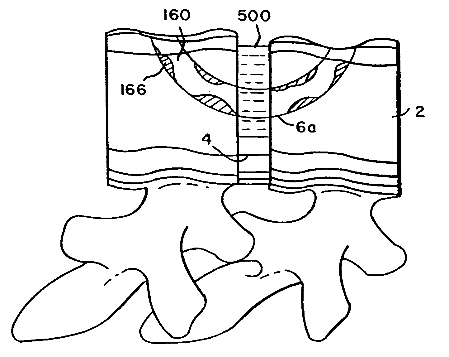
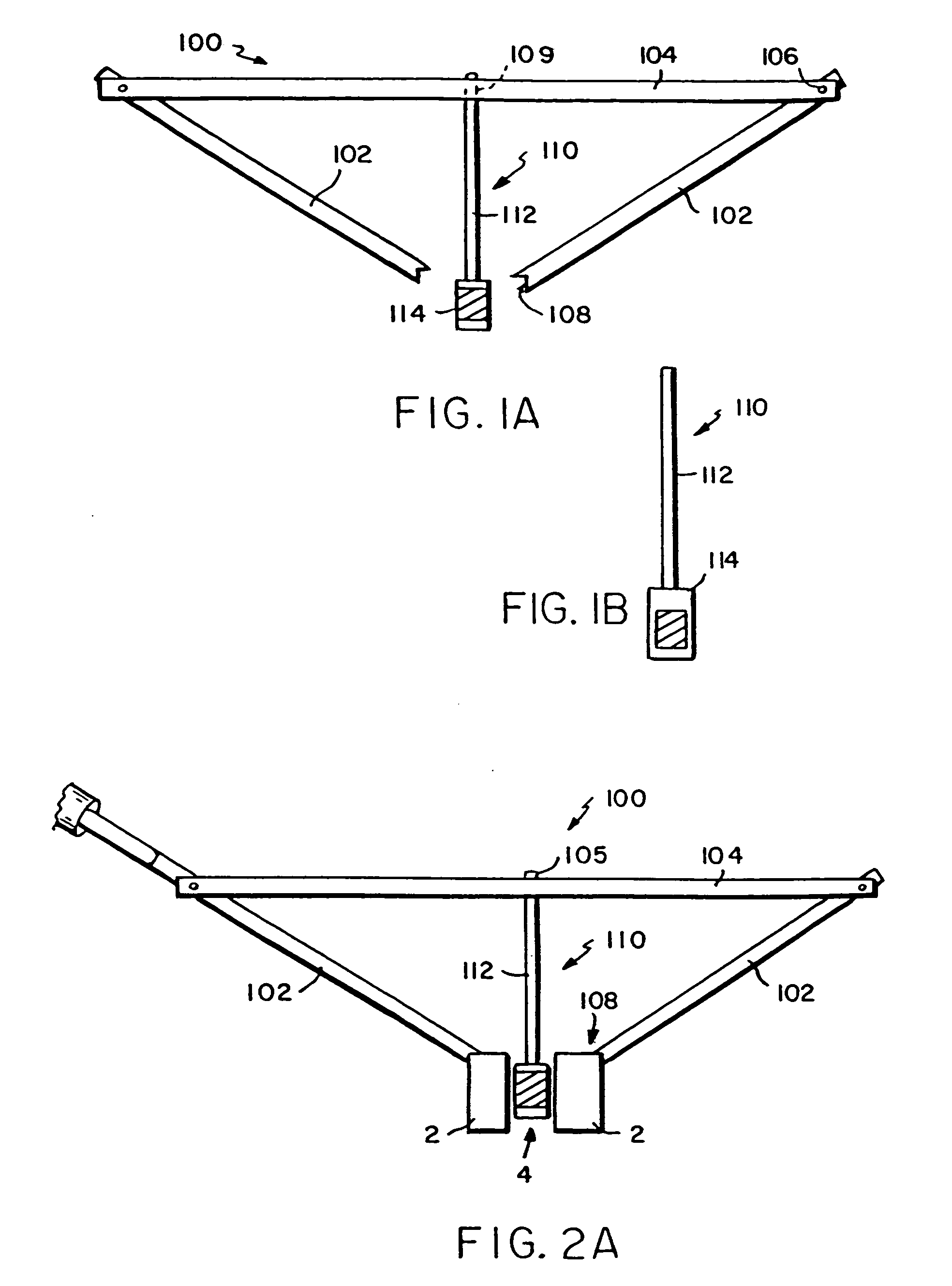
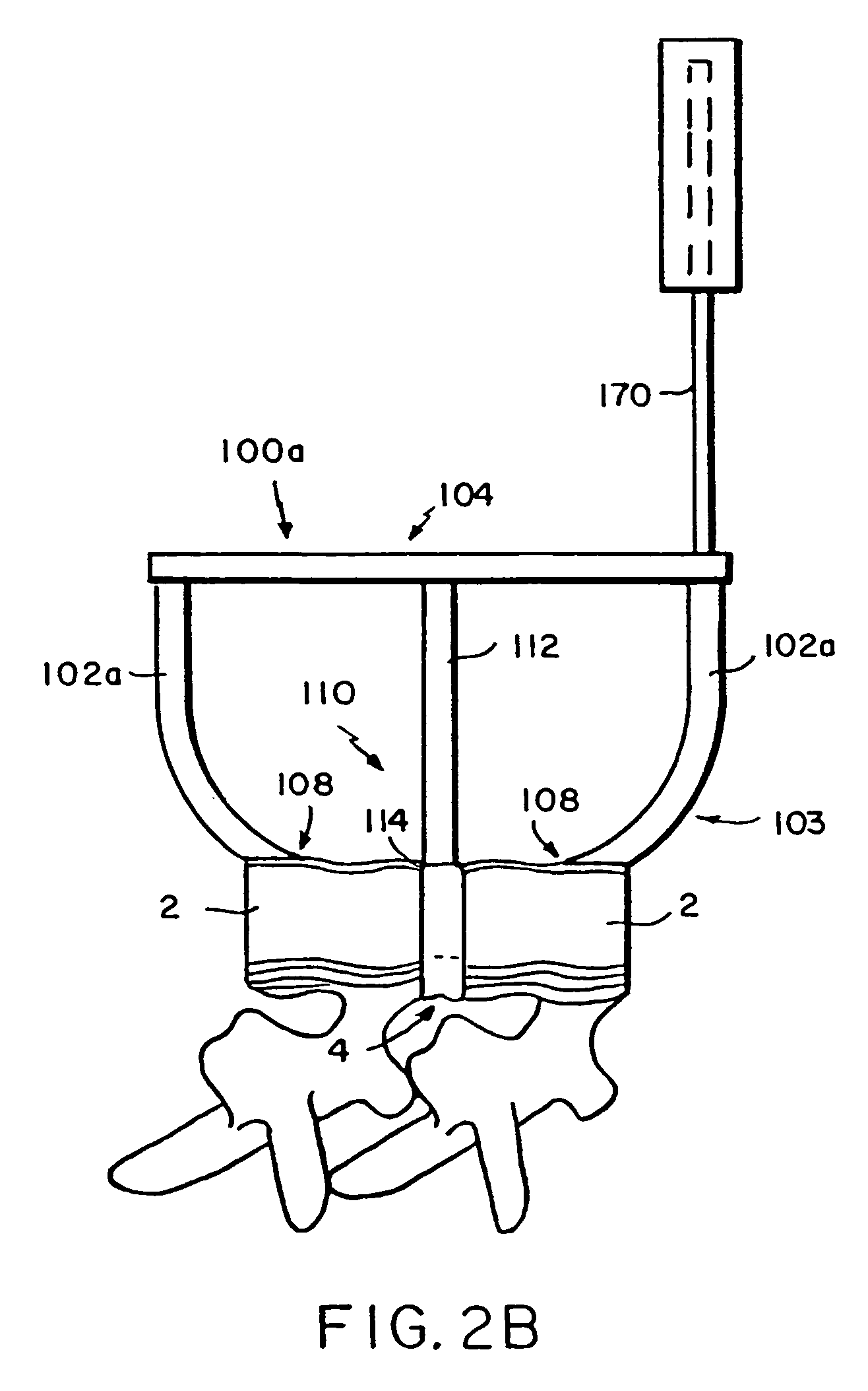
[0060]Referring now to the various figures of the drawing wherein like reference characters refer to like parts, there is shown in FIGS. 1–2 various schematic views of a drill guide or positioning jig 100 that positions or aligns the drill bits before making the holes in each of the vertebral bodies 2. The positioning jig 100 includes two guide sleeves 102, a cross member 104 and an intervertebral spacing member 110. Each guide sleeve 102 preferably is a hollow tubular member having a lumen or passage therein for receiving and guiding the means for forming at least the initial aperture in the adjacent vertebrae such as a drill bit 150 (FIG. 3B). As indicated elsewhere herein, the aperture may be formed using other techniques such as the ablation of bone by an energy source, e.g., high-pressure water, high-pressure air, ultrasound, or a laser. As such, it shall be understood that the internal sizing and configuration of the guide sleeves is established to accommodate the particular m...


PUM

PropertyMeasurementUnit
Forceaaaaaaaaaa
Diameteraaaaaaaaaa
Sizeaaaaaaaaaa

Abstract

Featured are a method and apparatus for fixing adjacent vertebrate of a spine that avoids the need and associated problems with prior cage or straight rod and screw systems. Methods and apparatus of the invention utilize a new implant member, which preferably is arcuate. Preferred methods of the invention for stabilizing adjacent vertebrae of the spine, include steps of providing a positioning apparatus including two guide sleeves, each guide sleeve having a long axis and locating the two guide sleeves with respect to the adjacent vertebrae such that a vertex formed by the long axis of each guide sleeve is located in the intervertebral space for the adjacent vertebrae. The method further includes forming an aperture in each of the adjacent vertebrae using the guide sleeves and inserting an implant into the apertures formed in each of the adjacent vertebrae so that the implant extends between the adjacent vertebrae and through the intervertebral space. In an alternative method a cutting fixture including a pivot arm is secured to the adjacent vertebrae and a cutting device is secured to the pivot arm. The pivot arm and cutting device are configured and arranged so that rotation of the pivot arm about a particularly located pivot point allows the cutting device to form the aperture in each of the adjacent vertebrae. Another alternative method for fixing adjacent vertebrate of a spine includes the step of forming a common channel in and between the adjacent vertebrae and inserting a biscuit implant in the common so as to bridge between the adjacent vertebrae.

Description

[0001]This application claims the benefit of U.S. Provisional Application Ser. No. 60 / 133,356 filed May 10, 1999, and of U.S. application Ser. No. 09 / 536,732, filed Mar. 28, 2000, which applications are incorporated herein by reference in their emtirety.BACKGROUND OF THE INVENTION[0002]1. Field of the Invention[0003]The present invention generally relates to methods, systems and apparatuses for bony fixation, more particularly to methods, systems and apparatuses adapted for fixing the bones of the spine, and to methods, systems and apparatuses adapted for securing a prosthetic device within the bones of the human body, more specifically securing a prosthetic device within the bones of the spine.[0004]2. Background of the Invention[0005]Fixation or fusion of vertebral columns with bone or material, rods or plates is a common, long practiced surgical method for treating a variety of conditions. Many of the existing procedures involve the use of components that protrude outwardly, whic...

Claims


Application Information

Patent Timeline
IPC IPC(8): A61B17/70A61B17/56A61B17/00A61B17/02A61B17/15A61B17/16A61B17/17A61B17/32A61B17/58A61B17/88A61B17/92A61B19/00A61F2/00A61F2/02A61F2/28A61F2/30A61F2/44A61F2/46
CPCA61B17/15A61B17/1642A61B17/1671A61B17/1757A61B17/320016A61B17/70A61B17/7083A61B17/92A61F2/4455A61F2/4611A61B17/1604A61B17/7011A61B2017/00004A61B2017/0256A61B2019/481A61F2002/4627A61F2310/00365A61F2002/4687A61B2090/08021
Inventor CARL, ALLENHART, RICKY D.WINKLER, JOSEF K.
Owner K2M
Why Eureka
Try Eureka