Process for removal of intermediate hydrogen from cascaded polyolefin slurry reactors

a technology of cascaded polyolefin and intermediate hydrogen, which is applied in the field of olefin polymerization in slurry reactors, can solve the problems of increasing the cost of blending operation, and generally inferior physicochemical properties of multimodal resin produced by blending

Inactive Publication Date: 2005-08-02
EQUSR CHEM LP
View PDF15 Cites 29 Cited by
  • Summary
  • Abstract
  • Description
  • Claims
  • Application Information

AI Technical Summary

Benefits of technology

[0021]These and other objects have been achieved through use of a multiple stage polymerization process wherein in a first stage, a hydrogen-mediated, light solvent slurry polymerization is employed to produce a slurry of a polymer of a given molecular weight, hydrogen is substantially removed from a product slurry stream without separating all the light solvent to produce a substantially hydrogen-free and pumpable slurry, and this slurry is then introduced into a second slurry reactor employing a lower concentration of hydrogen than the prior reactor. The removal of hydrogen between the two series-connected reactors is achieved through the use of multistage flash drums between prior and subsequent reactors, warm light solvent slurry medium from another portion of the process being added to dilute high solids effluent from a first flash drum.

Problems solved by technology

One disadvantage of such blended resins is that blending constitutes an additional process step.
The blending operation not only adds additional cost to the resin, but moreover, the multimodal resins produced by blending have generally inferior physicochemical properties as compared to multimodal resins having been produced by “in situ” routes.
Such products are generally inferior in their processing properties, especially for applications such as film production.
Although this process offers advantages in capial and installed costs relative to multi-reactor processes, the design and synthesis of dual site catalysts is difficult.
An additional process disadvantage is that use of a single reactor reduces the number of process parameters that can be manipulated to control polymer properties.
However, molecular weight is regulated by the presence of hydrogen in both reactors, with the second reactor having higher hydrogen concentration than the first reactor, thus limiting the types of interstitially mixed polymers which may be produced.
Polymerization at lower hydrogen pressure in the second reactor is not possible.
In addition, the polymer formed in each reactor is limited to a specific weight percentage range relative to the weight of the final product.
Continuous takeoff is said to produce inferior products.
These processes do not allow operation of the second reactor at lower hydrogen concentration than the first reactor.
Moreover, limiting olefin comonomer incorporation to only the first reactor limits the types of polymers which may be produced.
The inability to add significant comonomer to the second stage or to limit comonomer incorporation in the first stage detracts from the ability to produce a wide variety of polymers.
Moreover, the catalyst choice is limited to those which consume hydrogen when a single catalyst is used.
Both the U.S. Pat. Nos. 6,221,982 and 6,291,601 processes as well as the process of WO 98 / 58001 are inefficient in both monomer usage and thermal loading, since the hydrogenation reaction consumes ethylene, producing ethane by hydrogenation.
Moreover, in the U.S. Pat. Nos. 6,221,982 and 6,291,601 processes, an additional relatively expensive hydrogenation catalyst which contributes little to polymer production must be added.
Finally, all three processes require substantially homopolymerization in at least the first reactor, thus limiting the types of polymers which may be produced.
However, in the case of low boiling solvents such as propane, butane, and isobutane, efficient separation of hydrogen is difficult.
However, the patent contains no disclosure of any apparatus suitable for removing hydrogen from the first reactor product stream.
Moreover, the necessity to restrict the first polymerization to homopolymerization is limiting.

Method used


Image

  • Process for removal of intermediate hydrogen from cascaded polyolefin slurry reactors

Examples


example 1

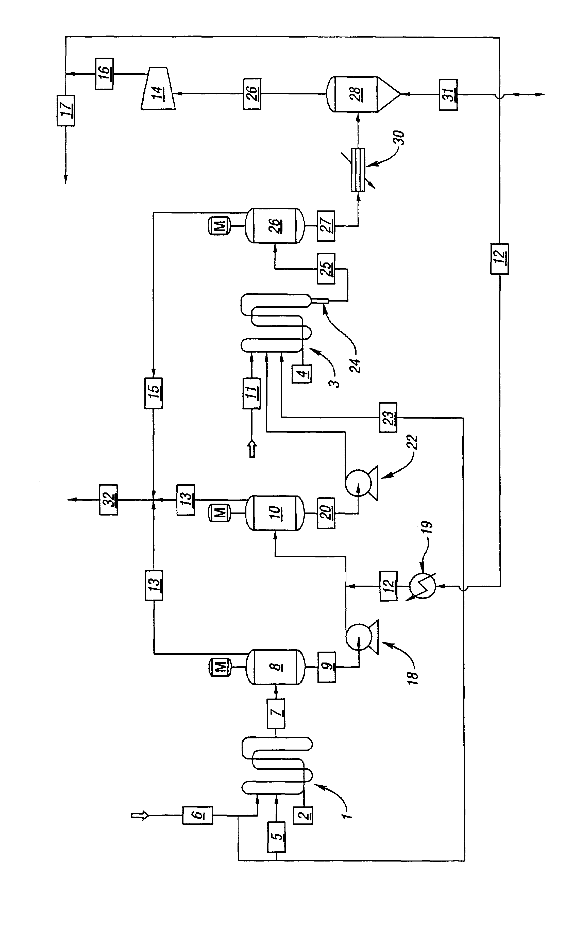
[0047]The example assumes that two vertical slurry loop reactors will be cascaded in series, with a two stage flash drum intermediate hydrogen removal system located between the two reactors. The first reactor in the series is denoted as the “A” reactor, and the second reactor is denoted as the “B” reactor. The loop reactors are tube-within-tube reactors wherein the inner tube, of 24″ inside diameter carbon steel, constitutes the polymerization reactor, and the outer tube, nominally 42″ inside diameter, defines the coolant capacity between the outer and inner tubes. The reactors are run solvent full, and nominally produce 60,000 lb / hr of a bimodal HDPE containing 1-butene as a comonomer. The ‘A’ reactor (1) is a 1500 ft, 31,000 gal six-leg reactor with a 2.0-hour residence time. The ‘B’ reactor (3) is a 2000 ft, 42,000 gal eight-leg reactor with a 1.4-hour residence time. Both reactor jackets are significantly oversized, thus providing the capability for reactor operations at higher...


PUM

PropertyMeasurementUnit
polydispersityaaaaaaaaaa
boiling pointaaaaaaaaaa

Abstract

Multimodal polyolefin polymers may be prepared in series-connected polymerization reactors where a prior reactor is a slurry reactor employing light solvent as the slurry medium and hydrogen to limit polymer molecular weight, the polymer product from the prior reactor being substantially freed of hydrogen prior to entry into a subsequent polymerization reactor operating at low hydrogen pressure to produce a high molecular weight olefin. The economics and operating performance of such a series slurry reactor polyethylene process can be significantly improved through the use of an intermediate slurry transfer system and hydrogen removal apparatus that employs flash drums in series in conjunction with a warm recycle solvent slurry diluent.

Description

BACKGROUND OF THE INVENTION[0001]1. Field of the Invention[0002]The present invention pertains to the field of olefin polymerization in slurry reactors. More particularly, the present invention pertains to a process for transferring a polyolefin / hydrocarbon solvent slurry from a first, hydrogen rich slurry reactor to a second reactor operated with a low and carefully controlled hydrogen concentration with concomitant removal of hydrogen from the first reactor discharge slurry stream. Within the context of the present invention, hydrogen refers to diatomic hydrogen.[0003]2. Background Art[0004]Polyolefins, particularly polyethylene and polypropylene, are produced in large amounts worldwide by polymerization of olefin monomers. The polyolefin products are employed in numerous products produced by a variety of fabrication processes, including, inter alia, extrusion, injection molding, resin transfer molding, blow molding, roto molding, and the like. Both the ultimate product physico-ch...

Claims


Application Information

Patent Timeline
Patent Type & Authority Patents(United States)
IPC IPC(8): C08F6/00C08L23/00C08F210/00C08L23/08C08F210/16C08L23/02C08F2/00
CPCC08F6/003C08F210/16C08L23/0815C08L23/00C08F2/14C08F2/00B01J2219/00006B01J2219/0004C08L23/02C08L2205/02C08L2308/00C08L2666/06C08F210/14C08F2500/05C08F210/06C08F210/08Y10S526/905
Inventor MCGRATH, PATRICK J.
Owner EQUSR CHEM LP
Why Eureka
Try Eureka