Optical connector

a technology of optical connectors and connectors, applied in the field of optical connectors, can solve problems such as noise interference of laser diodes, and achieve the effects of reducing the length of optical connectors, improving coupling efficiency, and precise circularity

Inactive Publication Date: 2005-08-09
HUNG CHEN HUNG
View PDF7 Cites 2 Cited by
  • Summary
  • Abstract
  • Description
  • Claims
  • Application Information

AI Technical Summary

Benefits of technology

[0007]It is an object of the present invention to provide an optical connector comprising a hollow, cylindrical shroud comprising a cylindrical section, a bore defined within the cylindrical section, the bore having a diameter to allow an optical fiber connector to fit therein and allow the same to plug or unplug a predetermined number of times, the bore being terminated at an opening in the bottom of the cylindrical section; a cylinder axially extended a predetermined distance from a center of the bottom of the cylindrical section, the cylinder comprising a longitudinal hole with an optical fiber fitted therein wherein a precise circularity in each of the bore and the longitudinal hole and coaxial characteristics of the same are obtained by forming the shroud and the cylinder by electrical casting, and a longitudinal axis of the bore is coaxial with a core of the optical fiber; and an annular flange formed integrally in a bottom of the shroud by electrical casting or injection molding, the flange being adapted to fasten either a laser diode element or a light detection element. By utilizing the present invention, a number of advantages such as significant reduction in the length of the optical connector, increase of coupling efficiency, a precise circularity in each of the cylinder, the flange, and the shroud, a precise coaxial characteristic of the optical connector, alignment of the light emitting position of the laser diode element with the optical fiber, and increase of performance can be obtained.
[0009]In one aspect of the present invention a longitudinal slit is formed on a surface of the shroud, the slit being adapted to provide a sufficient flexibility of the optical connector for withstanding the predetermined times of plugging or unplugging.
[0010]In another aspect of the present invention a slope is formed by shaving the bottom of the cylinder. The slope is adapted to prevent reflected light from directly impinging on the laser diode element. Otherwise, the laser diode element may be interfered by noise.

Problems solved by technology

Otherwise, the laser diode element may be interfered by noise.

Method used


Image

  • Optical connector
  • Optical connector
  • Optical connector

Examples


Embodiment Construction

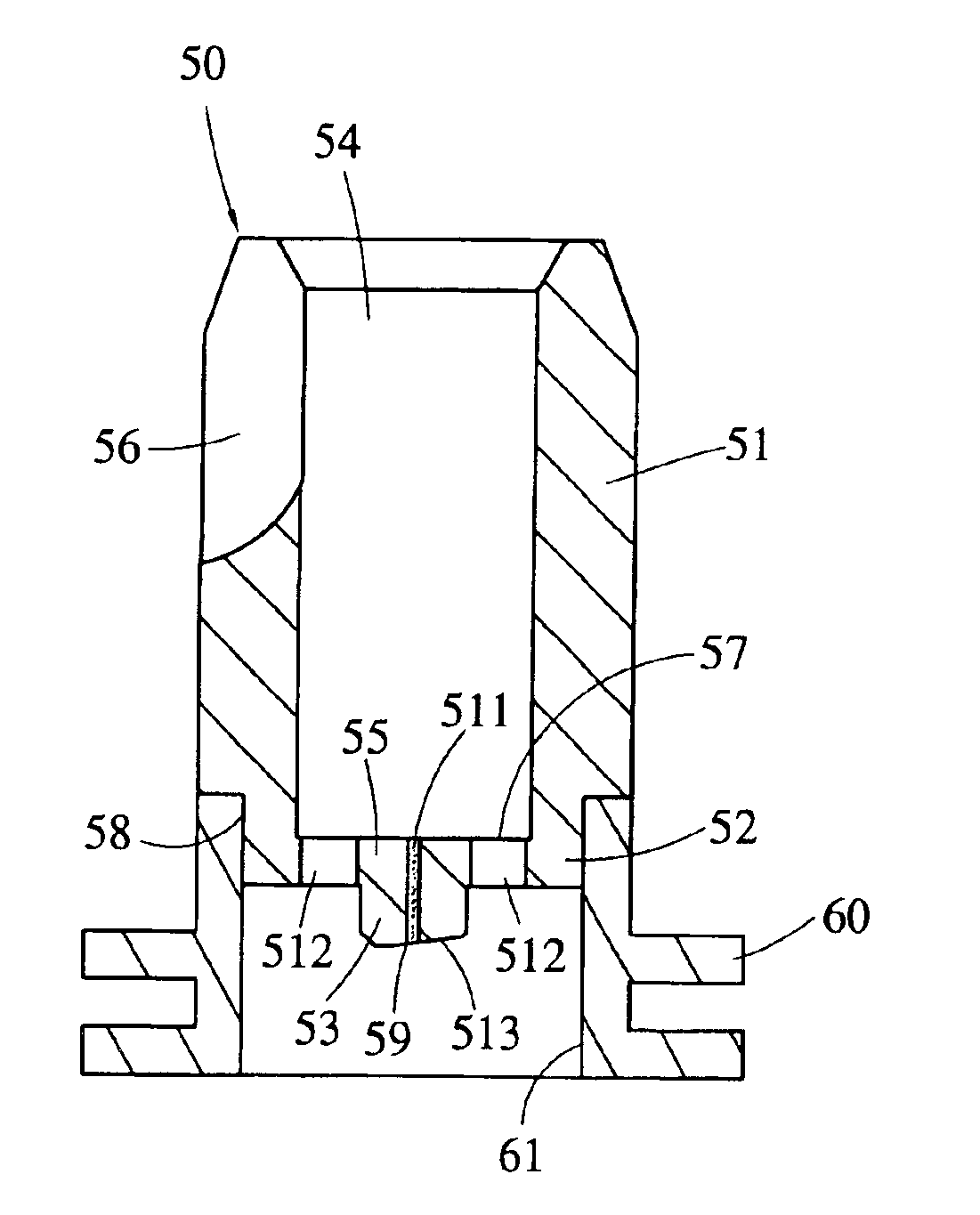
[0016]Referring to FIGS. 2, 3 and 4, there is shown an optical connector constructed in accordance with a first preferred embodiment of the invention. The optical connector comprises a hollow, cylindrical shroud 10 and a cylinder 20 inside the shroud 10. The shroud 10 and the cylinder 20 are formed by electrical casting for obtaining a precise circularity in both inner and outer diameters of the optical connector and a precise coaxial characteristic of the optical connector as required. Each component of the shroud 10 and the cylinder 20 will be described in detail below.

[0017]The shroud 10 comprises a cylindrical section 11 and an annular flange 12 in the bottom of the section 11. A bore 13 is defined within the section 11. The bore 13 has a diameter to allow an optical fiber connector to fit therein and allow the same to plug or unplug for a maximum number of times. The bore 13 is terminated at an opening 16 in a bottom 14. A longitudinal slit 15 is formed on a surface of the sect...


PUM


Abstract

An optical connector including a hollow, cylindrical shroud having a section, a bore defined within the section, the bore being adapted to fit an optical fiber connector therein and allow the same to plug or unplug a predetermined number of times, the bore being terminated at a bottom opening of the section; a cylinder axially extended a predetermined distance from a center of the bottom of the section, the cylinder having a longitudinal hole with an optical fiber fitted therein wherein a precise circularity in each of the bore and the hole and coaxial characteristics of the same are obtained by forming the shroud and the cylinder by electrical casting; and an annular flange formed integrally in a bottom of the shroud by electrical casting or injection molding, the flange being adapted to fasten a laser diode element or light detection element.

Description

BACKGROUND OF THE INVENTION[0001]1. Field of the Invention[0002]The present invention relates to optical connectors and more particularly to such an optical connector with improved characteristics including higher coupling efficiency.[0003]2. Description of Related Art[0004]Conventionally, laser diodes are used as a light source element or detection elements are used as a light reception element in the current optical communication system. The laser diodes are encapsulated to form a laser diode element and the detection elements are encapsulated to form a light detection element respectively. Either laser diode element or light detection element can be coupled to the bottom of an optical connector to form either a light emitting module or a light reception module by laser welding. The section of a conventional optical connector is shown in FIG. 1. The connector comprises a hollow, cylindrical shroud 1, a sleeve 2 coaxially fitted in the shroud 1, a cylinder 3 coaxially fitted in a l...

Claims


Application Information

Patent Timeline
Patent Type & Authority Patents(United States)
IPC IPC(8): G02B6/42
CPCG02B6/4292
Inventor HUNG, CHEN-HUNG
Owner HUNG CHEN HUNG
Why Eureka
Try Eureka