
Continuous impregnation of long fibers with resin for manufacturing elongate composite elements

Inactive Publication Date: 2005-08-09
CONCEPTION & DEV MICHELIN SA
View PDF47 Cites 31 Cited by
  • Summary
  • Abstract
  • Description
  • Claims
  • Application Information

AI Technical Summary

Benefits of technology

[0010]Preferably, the stabilization stage continues until said composition forms a solid medium (stage known as the gelling stage or therebeyond), so that the product is sufficiently cohesive to be capable of subsequent handling, for example to be capable of undergoing other treatments or of being used as an intermediate product incorporated into an end product, with the mechanical stresses which that entails, without the risk of “wringing” of the fibers, during which the amount of resin in the preform would diminish in an uncontrolled manner. The aim of stabilization is thus preferably to achieve a minimum level of polymerization allowing the prevention of any outflow of resin upon subsequent treatment thereof (in effect, treatment of the composite or of the item into which it is incorporated) under the action of heat, or even of pressure. The aim of stabilization is also preferably to achieve a minimum level of polymerization allowing the stabilized pre-preg to be provided with resistance to buckling of its fibers under subsequent bending stress.
[0038]Advantageously, at least one of the tubings has a cross section which does not increase, but rather preferably converges, as it travels from the inlet orifice towards the downstream orifice. This offers a good compromise between minimum friction of the fibers against the walls and good tightness. Of course, the tightness of the tubing in question is only relative. From the perspective of dynamic operation, this means that the leakage of air towards the vacuum chamber is low relative to the air evacuation capacity of the vacuum pump used. In practice, resin leakage towards the vacuum chamber is zero, given the viscosity of the resin, the pressure differential between the vacuum chamber and the impregnation chamber, the cross section and length of the passage between the vacuum chamber and the impregnation chamber and given the rate of feed of the fibers, which creates the effect of the resin returning towards the impregnation chamber.

Problems solved by technology

Unfortunately, pultrusion does not readily lend itself to high speed operation, as impregnation tends to be slow and difficult.
Furthermore, the kinetics of the heat transfer phenomenon considerably limits the rate of manufacture.
However, when it comes to the continuous manufacture of long components, it is not easy to impregnate the fibers correctly.
And the more it is wished to accelerate production rates, the more difficult it becomes to ensure perfect impregnation of the fibers with the resin.
Furthermore, the increasing commercial popularity of composite materials also depends on their cost price.

Method used


Image

  • Continuous impregnation of long fibers with resin for manufacturing elongate composite elements
  • Continuous impregnation of long fibers with resin for manufacturing elongate composite elements
  • Continuous impregnation of long fibers with resin for manufacturing elongate composite elements

Examples


Embodiment Construction

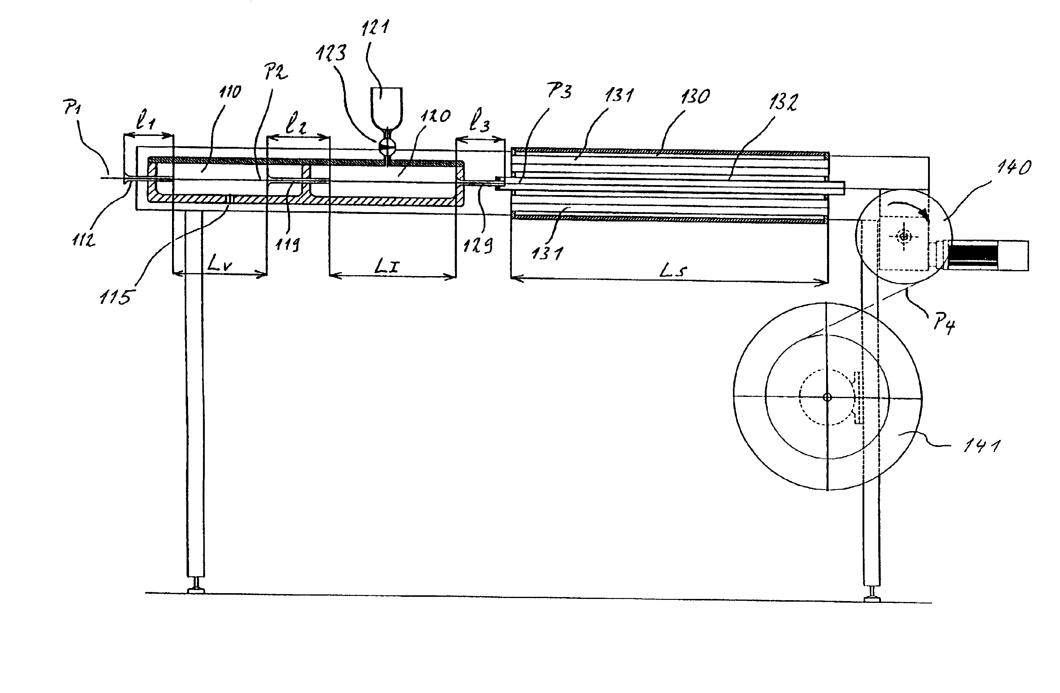
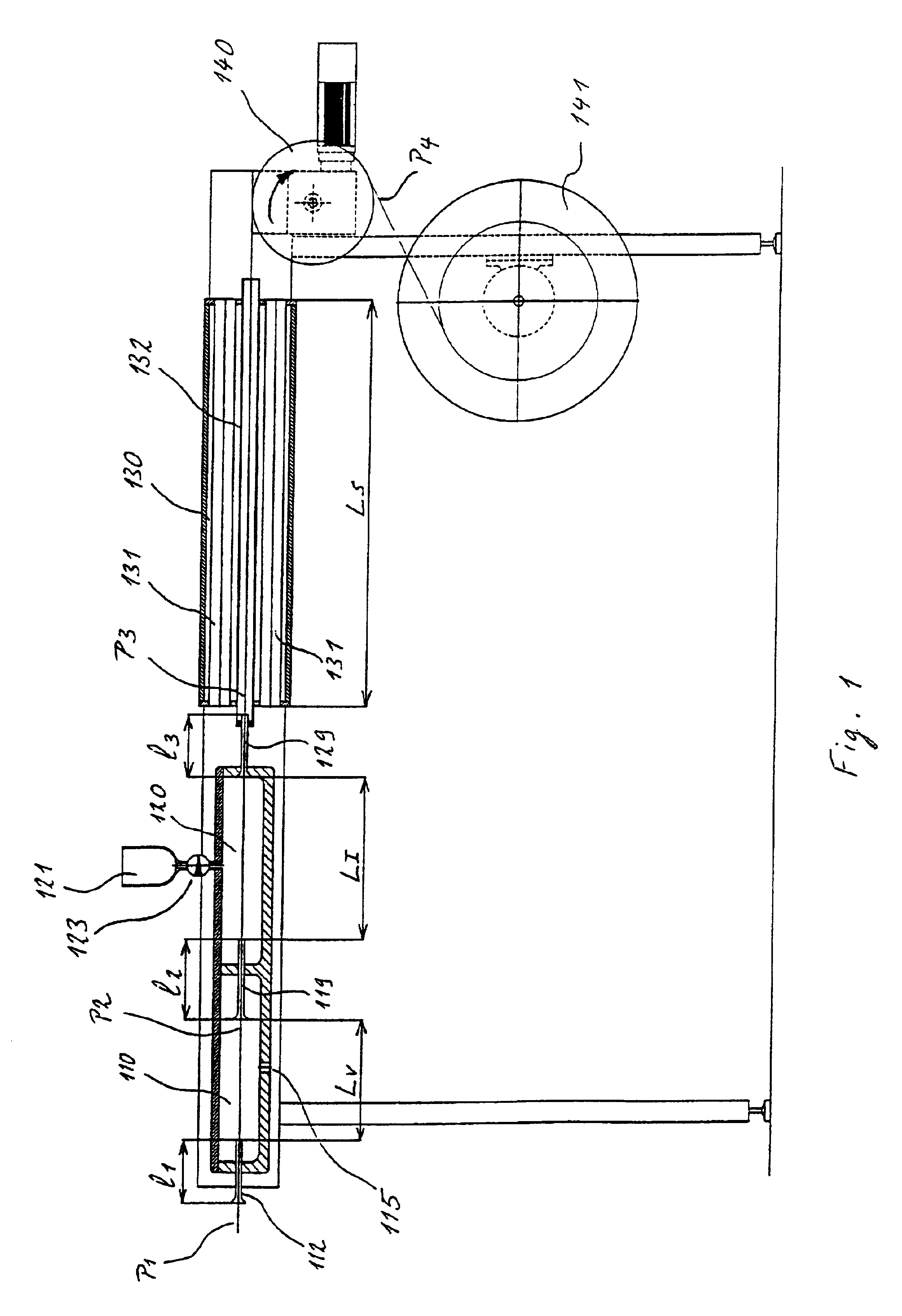
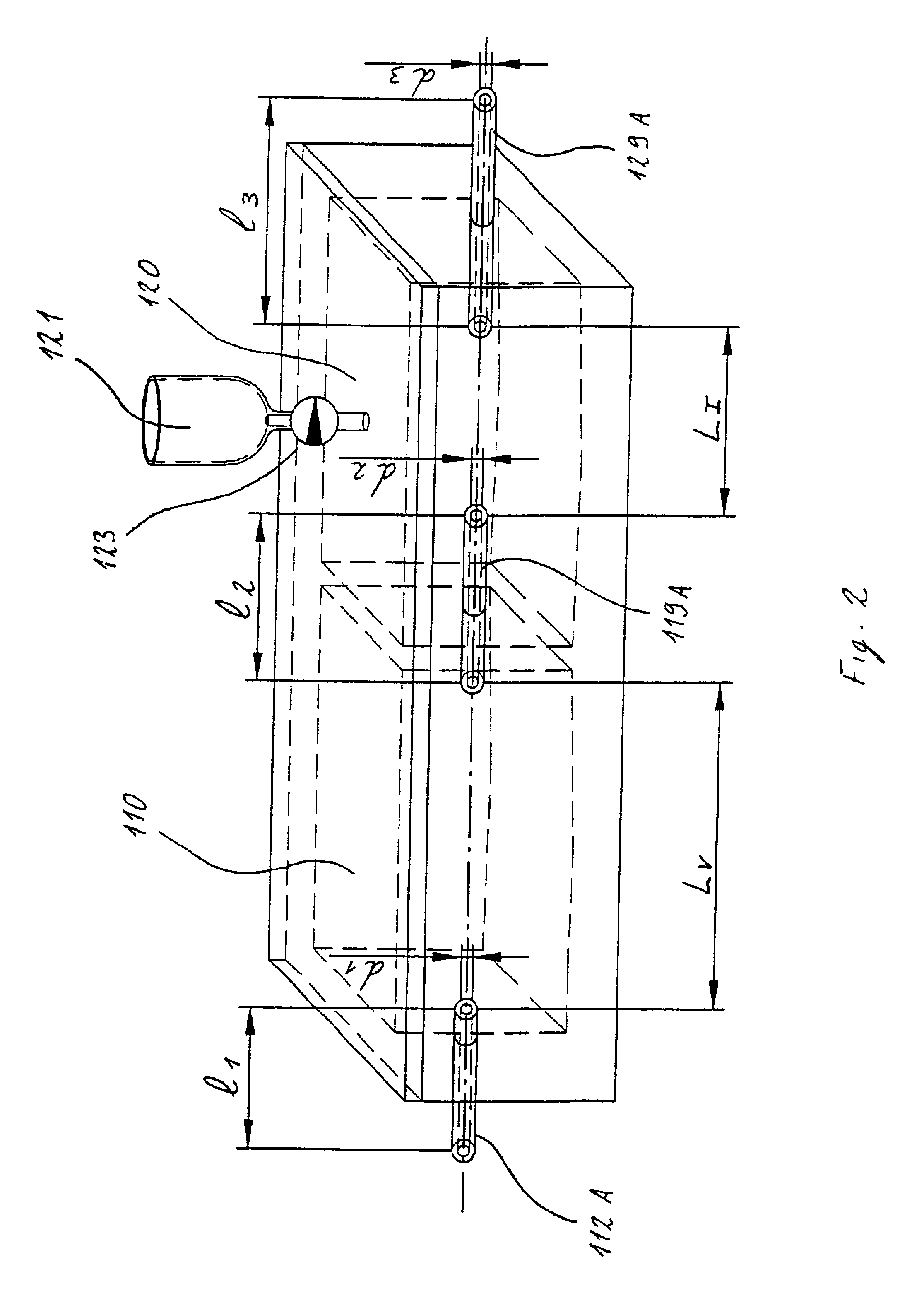
[0047]The invention lends itself to a wide range of shapes for the cross section of the composite material produced, comprising suitable fibers embedded in the selected resin. FIGS. 1 to 3 illustrate an installation which is more particularly suited to manufacture of an elongate composite element of round cross section. FIG. 1 shows the fibers P1 being continuously unwound from a reel. In general, the reinforcement fibers are supplied in rovings, that is to say in groups of fibers wound in parallel on a reel (for example, fibers, also known as filaments, are used which are sold under the name PPG 2001-300 TEX).

[0048]For example, the composite material exits in the form of a filament P4 of round cross section of any size, drawn by a winding device comprising a roller 140 and a receiving reel 141. The traction exerted by the roller 140 is what allows feed of the fibers in parallel along the installation.

[0049]FIG. 1 reveals in succession a vacuum chamber 110, an impregnation chamber 1...


PUM

PropertyMeasurementUnit
Temperatureaaaaaaaaaa

Abstract

An apparatus for manufacturing an elongate composite element in undefined lengths, the composite element containing reinforcement fibers embedded in a matrix based on a composition containing a curable resin, including a vacuum chamber, rigid-walled inlet tubing, an impregnation chamber, rigid-walled transfer tubing between the vacuum chamber and the impregnation chamber, a sizing die and, downstream of the sizing die, irradiation tubes providing radiation in the ultraviolet-visible spectrum to prepolymerize the resin.

Description

BACKGROUND OF THE INVENTION[0001]The present invention relates to the manufacture of a long elongate composite element, comprising long reinforcement fibers, embedded in a matrix of cured resin.[0002]It is becoming more and more common to use composite materials for manufacturing structural components or load-bearing components or reinforcement elements, owing to the ever better performance which may be achieved with composite materials. Composite materials often allow considerable weight savings to be made while achieving equivalent mechanical performance. Moreover, in applications where the composite material is subject to considerable stress, it is very important to be able to benefit fully from the reinforcing action of the fibers. This requires absolute mastery of the manufacture of composite elements.[0003]The role of the resin is to connect the fibers firmly to one another and to transmit stresses to the fibers. It is very important for the fibers to be totally impregnated an...

Claims


Application Information

Patent Timeline
IPC IPC(8): B29B15/10B29B15/12B29C70/04B29C70/52C08J5/24B29C70/06B29K101/10B29K105/08
CPCB29C70/521B29C70/525B29B15/125
Inventor HINC, HENRIMERALDI, JEAN-PAULVERDIS, ANTOINEGENOUD, FERNAND
Owner CONCEPTION & DEV MICHELIN SA
Learn More