Anti-reflective polymer constructions and method for producing same

Inactive Publication Date: 2005-08-09
3M INNOVATIVE PROPERTIES CO
View PDF70 Cites 63 Cited by
  • Summary
  • Abstract
  • Description
  • Claims
  • Application Information

AI Technical Summary

Benefits of technology

[0004]In a first aspect, the invention features an article that includes a plurality of polymer layers, each having a thickness no greater than about 1 micrometer and collectively forming a free-standing film. The layers are selected such that when the article is optically coupled to a surface of a substrate having a refractive index of about 1.50, the article reduces the reflectivity of the substrate at the surface over a wavelength range of interest by a factor of at least about 2 at normal angles of incidence. The article may be optically coupled to the substrate surface, e.g., by adhering it to the substrate surface. Materials are said to be “optically coupled” when the air space between them is replaced by a material with an index of refraction similar to that of the two articles, or when the air space is reduced in thickness to a value much less than a quarter wavelength.
[0017]In a fourth aspect, the invention features a process for preparing an article that includes co-extruding a plurality of polymer compositions with each other to form a plurality of polymer layers in the form of a free-standing film, the polymer layers being selected such that when the article is optically coupled to a substrate, the article reduces the reflectivity of the substrate over a wavelength range of interest.
[0022]The invention provides lightweight, relatively inexpensive, polymeric anti-reflective constructions that can be used alone or in combination with a number of materials, including multilayer polymeric polarizers and mirrors. The structure and properties of the anti-reflective construction can be tailored to render it effective over a selected portion of the electromagnetic spectrum. In addition, unlike conventional vacuum-deposited anti-reflective coatings, the polymeric anti-reflective constructions according to the invention can readily be aplied to non-planar (e.g., curved) surfaces such as cathode ray tubes.

Problems solved by technology

Such reflection is particularly undesirable in the case of, e.g., cathode ray tubes, liquid crystal displays, and windows because it causes glare and can reduce the brightness and contrast of a displayed image.

Method used


Image

  • Anti-reflective polymer constructions and method for producing same
  • Anti-reflective polymer constructions and method for producing same
  • Anti-reflective polymer constructions and method for producing same

Examples


Embodiment Construction

Structure

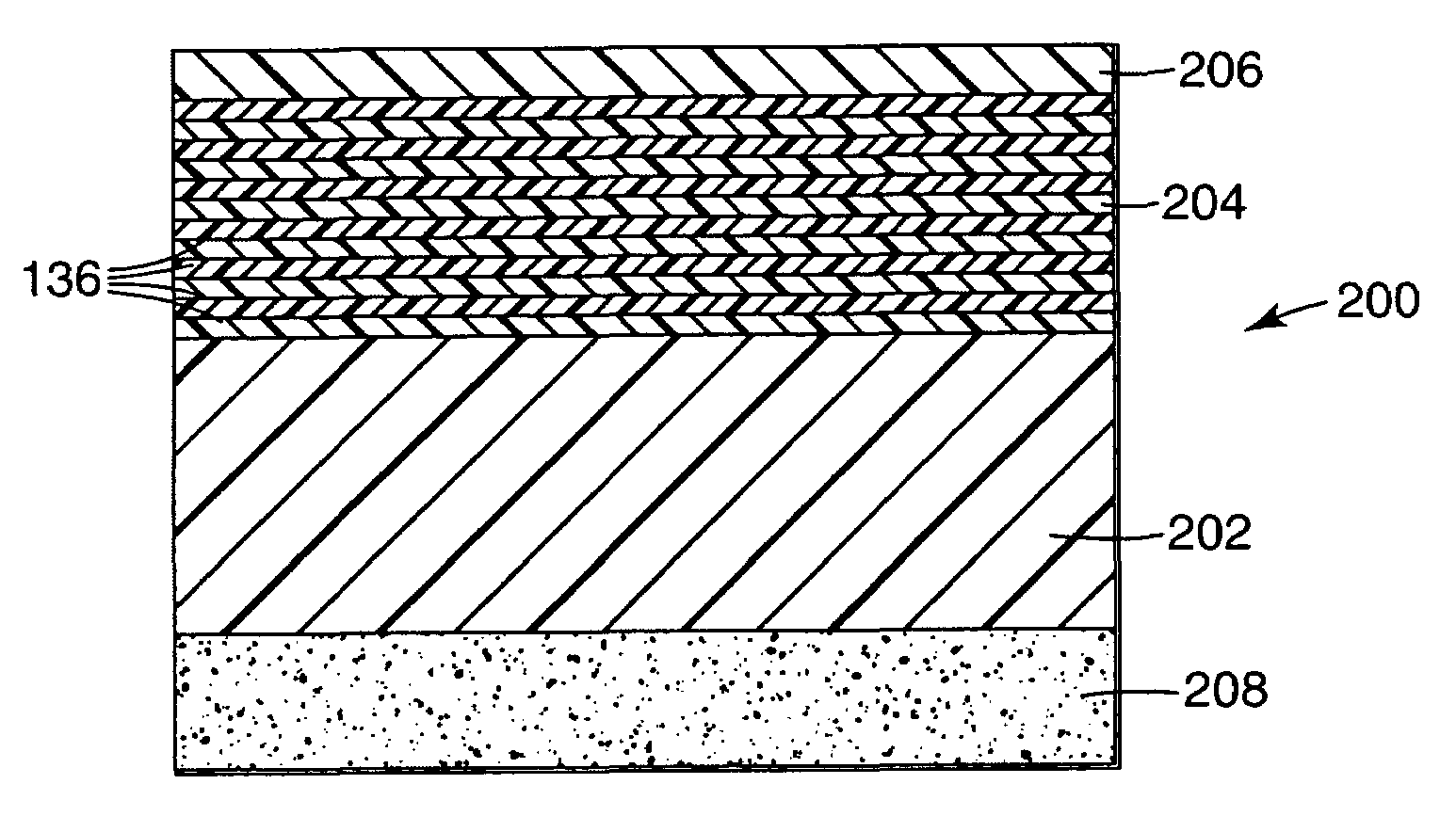
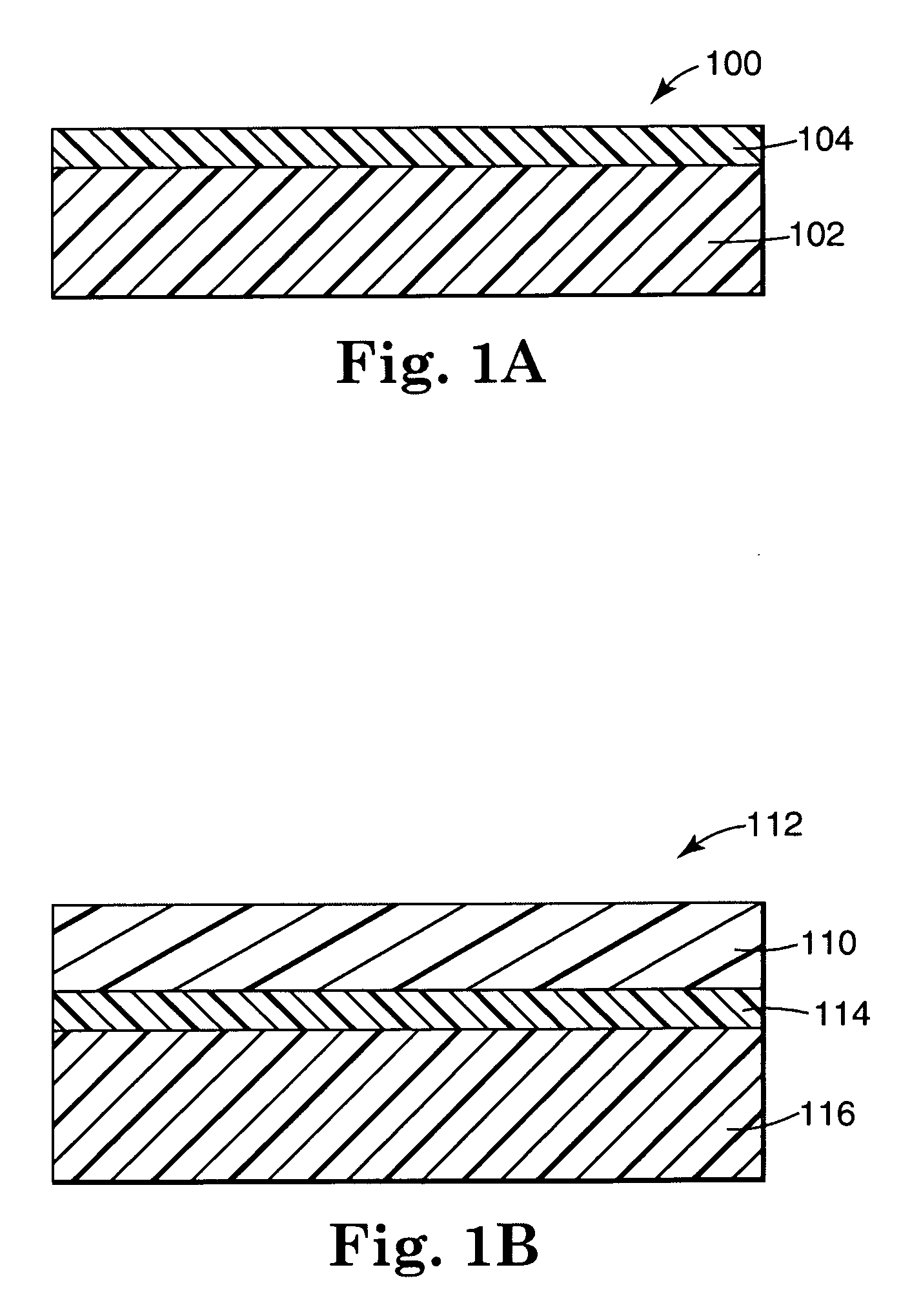
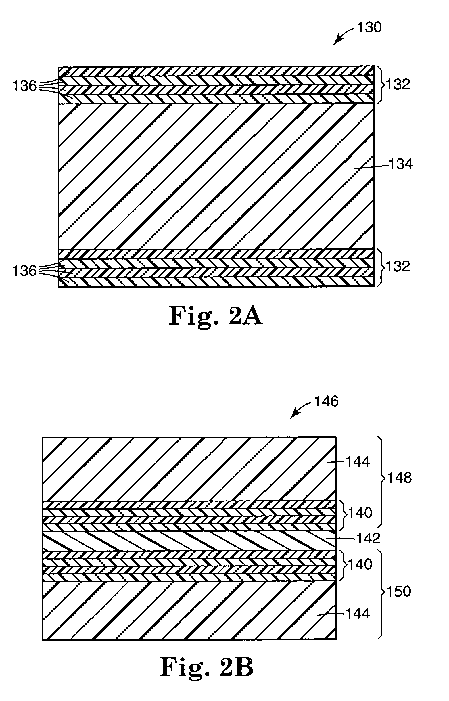
[0033]Anti-reflective (AR) constructions are preferably provided in the form of free-standing films, i.e., films having sufficient mechanical integrity that they can be readily handled without the need for additional reinforcing layers. The anti-reflective properties can be tailored to cover a selected range of electromagnetic frequencies, including portions of the visible, infrared (1R), and ultraviolet (UV) regions of the electromagnetic spectrum.

[0034]The AR constructions may be used alone (such that the film forms an interface with air) or optically coupled to one or both major surfaces of a base; in the latter case, the AR construction de-reflects radiation impinging upon the surface of the base at the base / AR construction interface. The AR construction may be adhered to the surface of the base. Preferably, however, it is formed simultaneously with the base by co-extrusion, as described in more detail, below. In addition, the base / AR construction article may itself be ...


PUM

PropertyMeasurementUnit
Thicknessaaaaaaaaaa
Wavelengthaaaaaaaaaa
Refractionaaaaaaaaaa

Abstract

Articles, including free-standing films, comprising a base comprising a polymer layer having a major surface; and an anti-reflective stack optically coupled to the base that reduces the reflectivity of the base at over a first wavelength range of interest. The anti-reflective stack comprises alternating layers of (i) high index polymer; and (ii) low index polymer. Methods of making such articles are also provided.

Description

BACKGROUND OF THE INVENTION[0001]This invention relates to providing anti-reflective properties.[0002]Anti-reflective layers, e.g., in the form of thin films, are used to prevent unwanted reflection at surfaces. Such reflection is particularly undesirable in the case of, e.g., cathode ray tubes, liquid crystal displays, and windows because it causes glare and can reduce the brightness and contrast of a displayed image.[0003]Traditional anti-reflective layers have been made from inorganic materials, e.g., magnesium fluoride, that are coated onto an optical element such as a glass lens. Using a quarter-wavelength thick anti-reflective layer can reduce the reflection considerably for the selected wavelength because of destructive interference.SUMMARY OF THE INVENTION[0004]In a first aspect, the invention features an article that includes a plurality of polymer layers, each having a thickness no greater than about 1 micrometer and collectively forming a free-standing film. The layers ar...

Claims


Application Information

Patent Timeline
IPC IPC(8): G02B1/11G02B1/10B32B7/02G09F9/00
CPCG02B1/111Y10T428/269Y10T428/24942Y10T428/24967Y10T428/2495Y10T428/31663Y10T428/3154Y10T428/31797Y10T428/31786Y10T428/31848G02B1/12
Inventor WEBER, MICHAEL F.OUDERKIRK, ANDREW J.
Owner 3M INNOVATIVE PROPERTIES CO
Why Eureka
Try Eureka