[0004]The above-identified copending related U.S.
patent application Ser. No. 09 / 826,422 of Maslov et al. identifies and addresses the need for an improved motor amenable to simplified manufacture and capable of efficient flexible operating characteristics. In a vehicle drive environment, it is highly desirable to attain smooth operation over a wide speed range, while maintaining a
high torque output capability at minimum
power consumption. Such a vehicle
motor drive should advantageously provide ready
accessibility to the various structural components for replacement of parts at a minimum of inconvenience. The copending related U.S. application incorporates
electromagnet poles as isolated magnetically permeable structures configured in an annular ring, relatively thin in the radial direction, to provide advantageous effects. With this arrangement, flux can be concentrated, with virtually no loss or deleterious
transformer interference effects in the
electromagnet cores, as compared with prior art embodiments. While improvements in torque characteristics and efficiency are attainable with the structure of the identified copending application, further improvements remain desirable.
[0005]To this end, the above-identified copending related U.S.
patent application Ser. No. 09 / 826,423 of Maslov et al. seeks to optimize rotor parameters such as the grade of the
magnet, the
energy density and the overall magnetic characteristics of the
magnet grade, the size and the dimensions of the
magnet that can adjust the permanence and the overall operating condition of the magnet when it is part of the rotor, the temperature stability of the magnet, the finishing,
coating and post
processing steps taken in manufacturing of the magnets for the intended application, the stability of the
magnetization over the curvilinear surface of the magnet, uniformity of the
radial polarization of the magnet, the adjacent gap between two separate magnets, the mechanical features of the edges of the magnets, and the return flux path of the magnet as provided by a back iron ring section.
[0006]In environments in which portability and size are important factors, the need exists for drive motors that are capable of a wide range of operating characteristics, without sacrificing complex control functionality. Brushless motor systems should have the capability to control each of a plurality of electronic switches to provide accurate commutation sequencing and appropriate application of power to the individual stator windings. The above-identified copending related U.S.
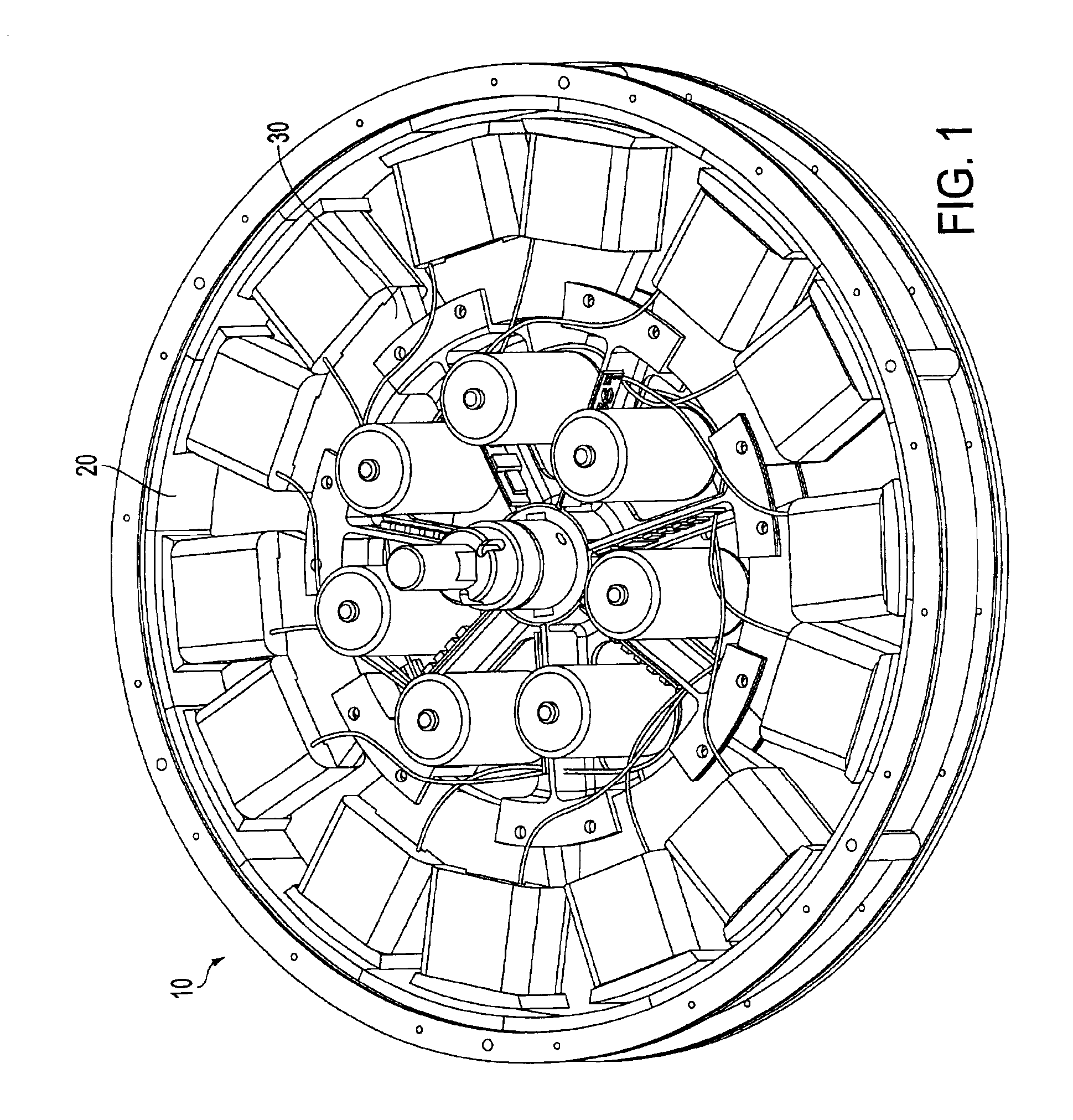
patent application Ser. No. 09 / 966,102 of Maslov et al. describes a motor structural configuration in which the control elements, which can be complex and diverse, are contained within the confines of the stator. The stator flux producing structure, streamlined to a relatively thin annular configuration to accommodate placement of the elements therein, nevertheless is capable of producing appropriate flux output while providing
high torque at low operating speeds.
[0007]Various advantages attributable to the provision of multiple separate stator magnetic paths in comparison to a single
common path in the stator body have been described above. Easy
accessibility to the interior of the stator and the structural and electrical components therein present additional opportunities for improved operation.DISCLOSURE OF THE INVENTION
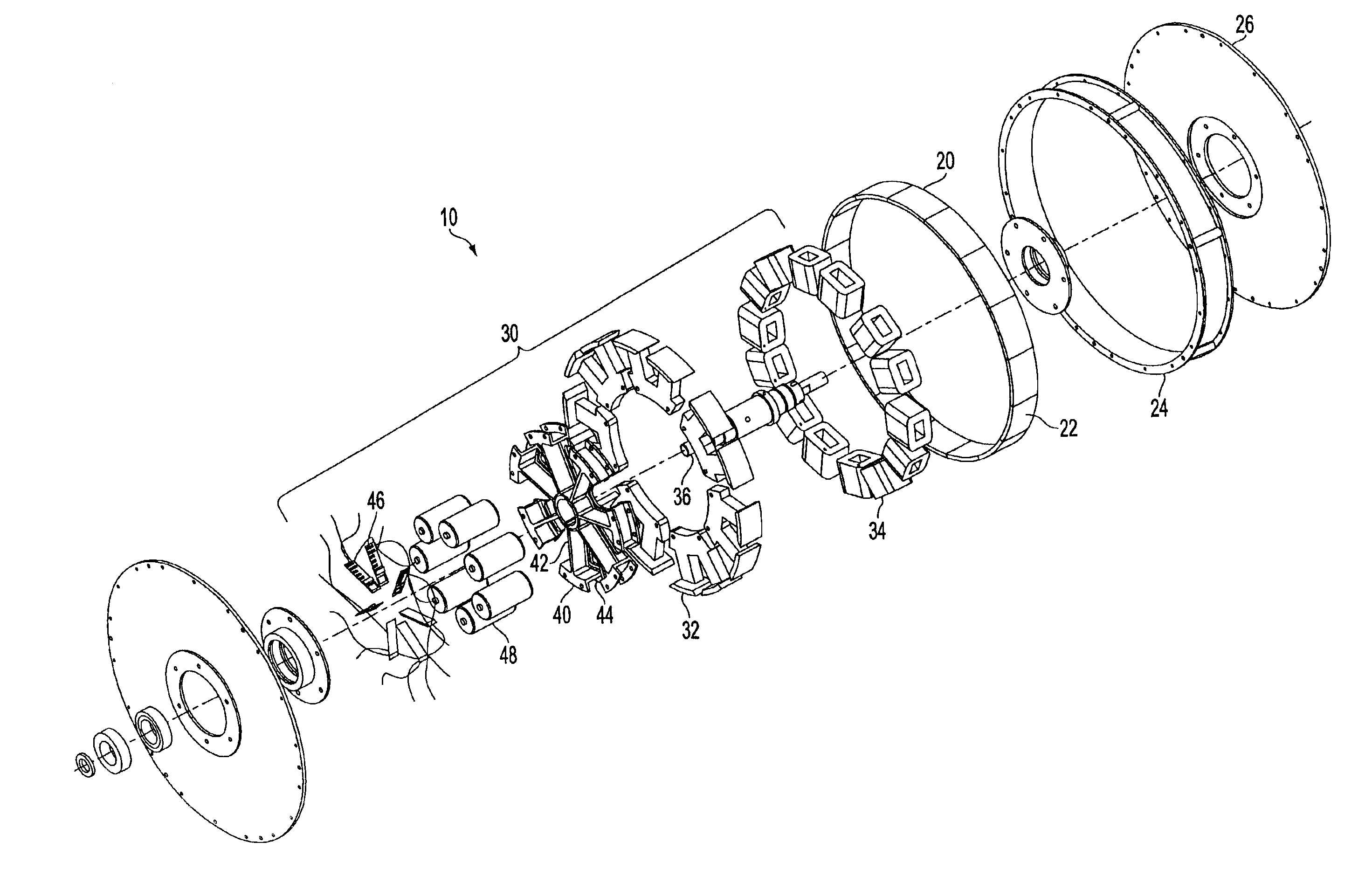
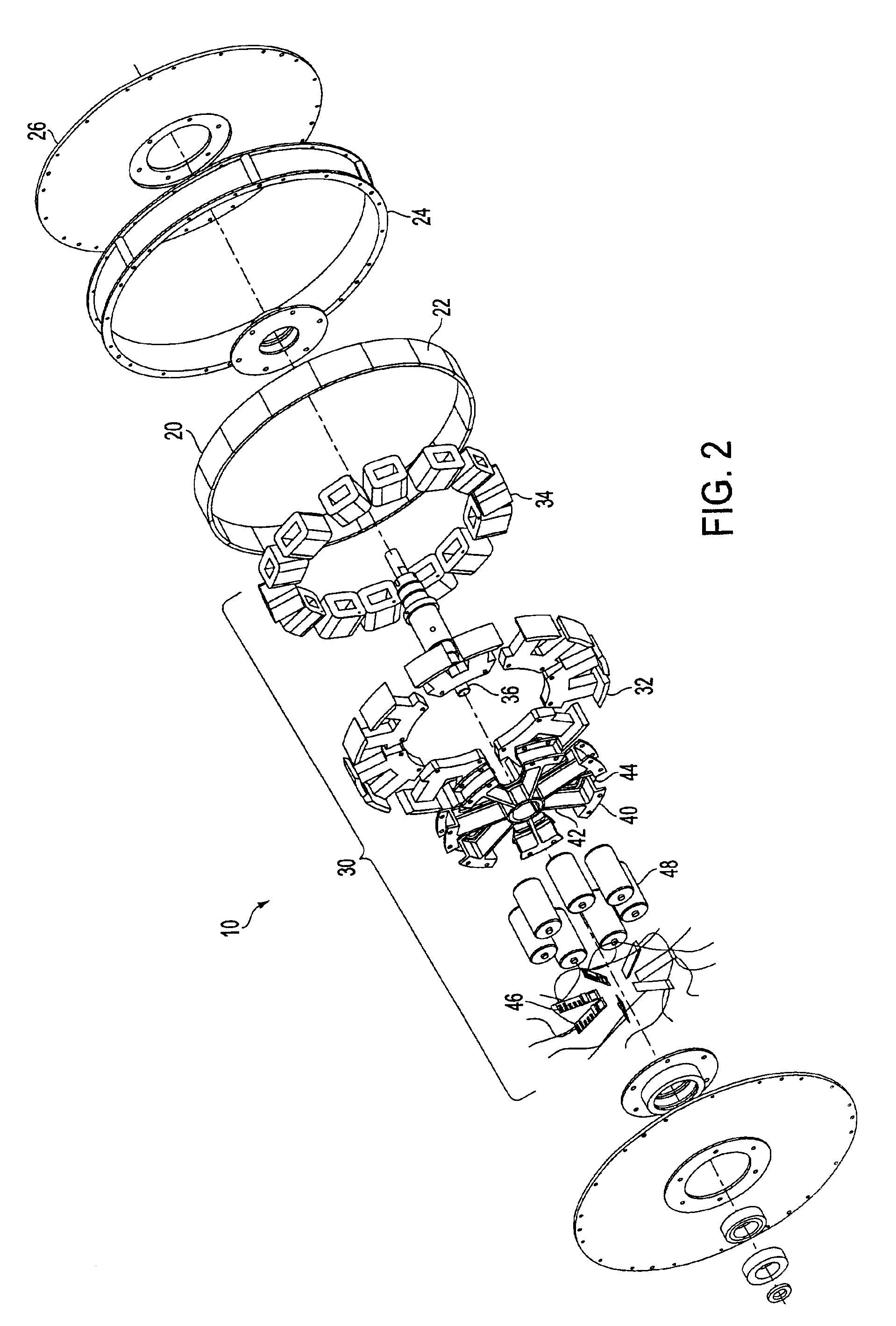
[0008]The present invention fulfills the above described needs, while providing additional benefits of the isolated individual pole pair arrangements disclosed in the identified Maslov et al. applications. The stator is formed of a plurality of individual power modules and corresponding core segments, each module comprising
electrical control and drive elements supplied by a power source incorporated within the stator. Such parallel architecture provides relatively independently controlled functionality for each module. Performance of each module individually may be measured in situ during normal operation or by running more extensive,
software controlled, diagnostic routines. Based on test results, a module can be automatically recalibrated, disconnected, or flagged for repair or replacement. Overall motor performance, determined by combining the characteristics of the independent modules, can be compared to original benchmarks to analyze various repair options for devising the minimum necessary action.
[0009]Each module and stator core segment can be individually installed and removed without disturbing the other units. Should a particular module or stator core segment fail, it can be deactivated without significantly affecting the overall performance of the remaining stator modules. Thereafter, the faulty element can be easily removed and tested externally while permitting the motor to operate with the remaining modules. The faulty component can then be identified and repaired or replaced. At a convenient time, the repaired or replacement unit can be easily reinstalled in its stator compartment.

