Power factor/tan deltatesting of high voltage bushings on power transformers, current transformers, and circuit breakers

a technology of power factor and delta, which is applied in the direction of dielectric property measurement, instruments, base element modifications, etc., can solve the problems of long shut-down time, expensive equipment disconnections, and loss of service equipment for whatever period of tim

Inactive Publication Date: 2005-08-09
WEIDMANN ELECTRICAL TECH
View PDF16 Cites 24 Cited by
  • Summary
  • Abstract
  • Description
  • Claims
  • Application Information

AI Technical Summary

Problems solved by technology

In practice, it has been very expensive to disconnect equipment for testing.
In addition to the man-power required to disconnect the HV equipment, connect it to test equipment and perform the test, the service of the equipment is lost for whatever period of time it takes to disconnect, make the test and reconnect.
If there are large numbers of transformers and circuit breakers, and other equipment to be tested, the shut-down can be lengthy and the loss of revenue to the power company very substantial.
Age and temperature contribute to such deterioration, particularly hot spots which may ultimately burn the paper.
Normal aging of HV equipment is a slow process that can take place over 30 to 40 years due to thermal, electrical and environmental effects.
Premature failure on the other hand is often a relatively sudden process that is not anticipated by periodic off-line tests.
Failure to detect insulation deterioration can result in disastrous consequences, ultimately causing heating of the equipment, fire and explosion.
Heat may generate various hydrocarbon gases from the oil used in the transformer and some of these gases, such as acetylene, are highly flammable and may be explosive.
The resulting explosion shatters porcelain insulators and sends pieces flying, damaging adjacent equipment.
In a sub-station, or other areas where multiple sets of equipment are employed, an explosion not only results in loss of the exploded device, but also may result in damage to other very expensive equipment, as well as posing substantial danger to personnel working in the area, or even to passers-by in some locations.
The eventual breakdown of insulation is a rapid avalanche of failing dielectric layers.
Damaged or deteriorated dielectric is associated with the following: 1) Increased dielectric losses (I2R) with other sources of heating may eventually fuel a mechanism of thermal runaway.
Most power companies are faced with the dilemma of taking equipment offline and testing it with consequent loss of revenue to the company, or, alternatively, leaving the equipment online without testing longer than it should be.
The latter course allows damage to occur and take its toll.

Method used


Image

  • Power factor/tan deltatesting of high voltage bushings on power transformers, current transformers, and circuit breakers
  • Power factor/tan deltatesting of high voltage bushings on power transformers, current transformers, and circuit breakers
  • Power factor/tan deltatesting of high voltage bushings on power transformers, current transformers, and circuit breakers

Examples


Embodiment Construction

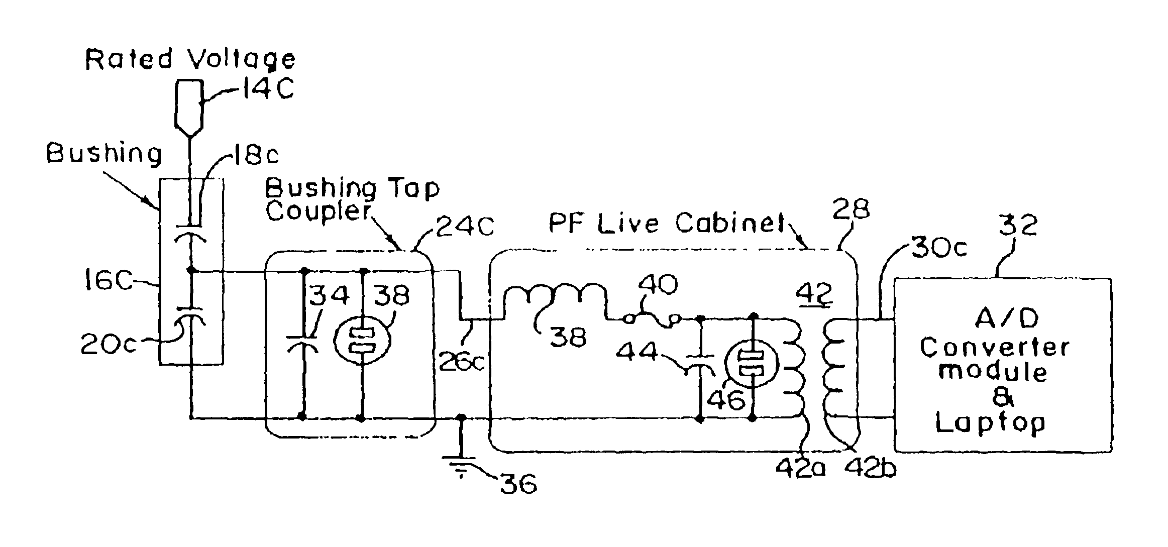
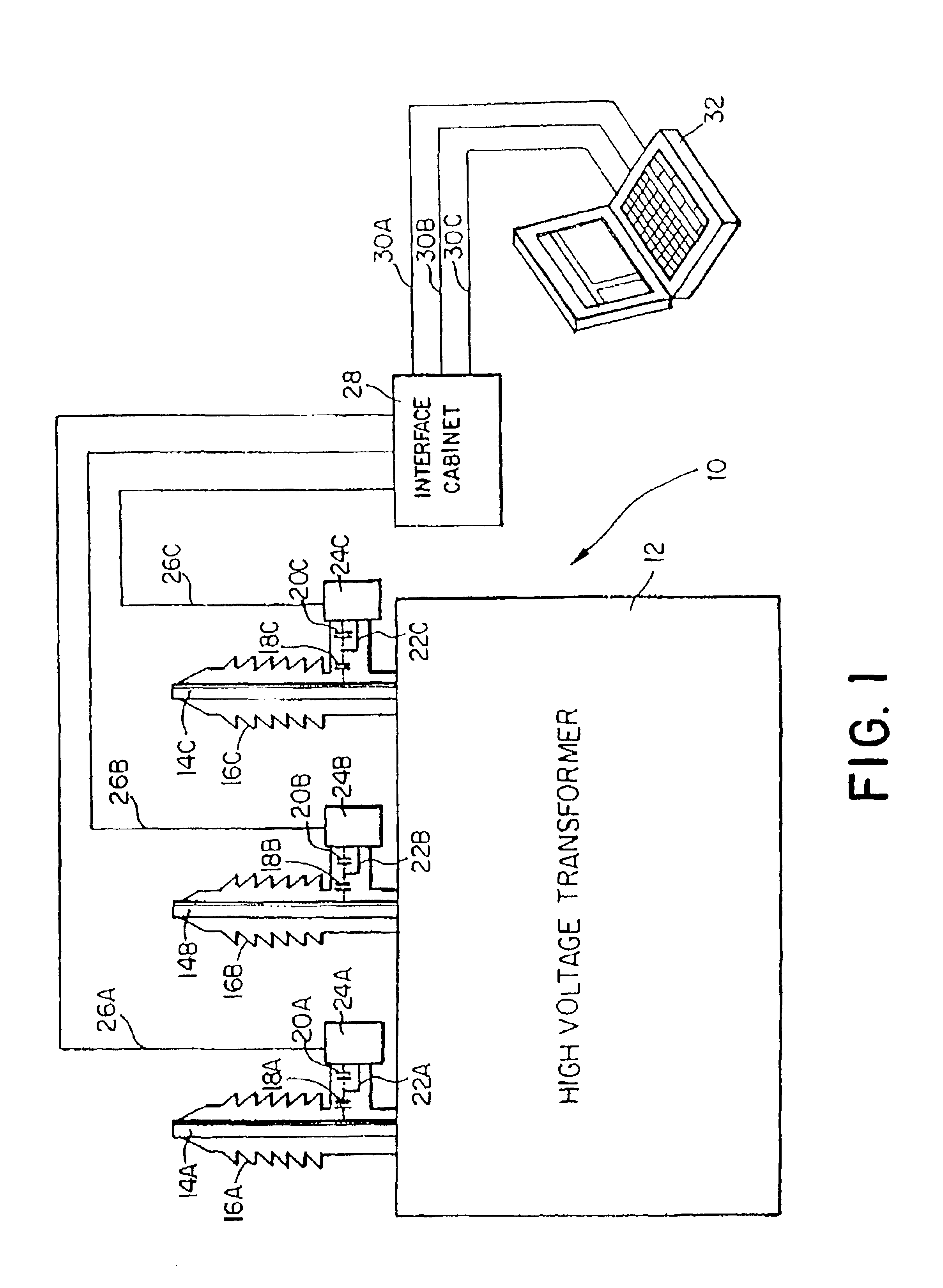
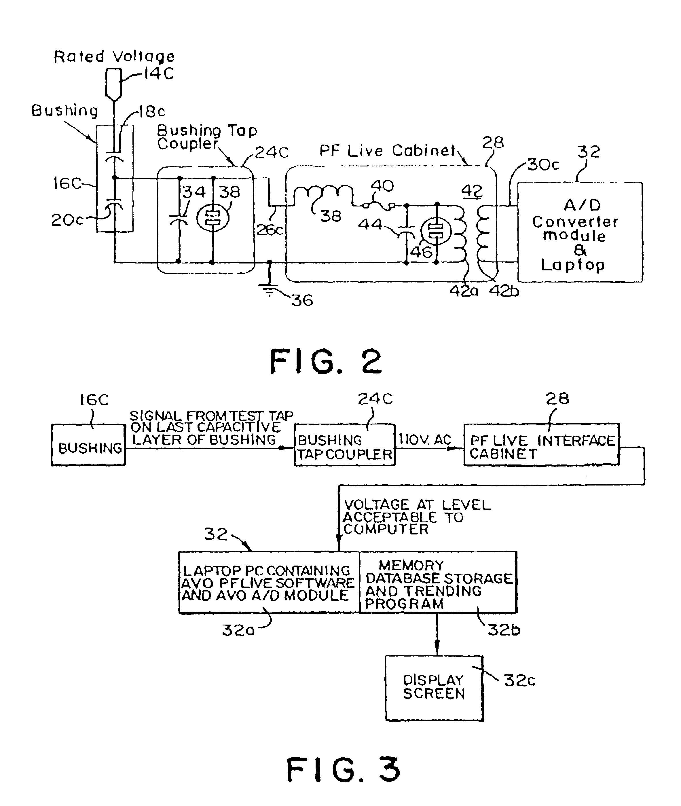
[0017]FIG. 1 shows very schematically a HV transformer generally designated 10. The transformer itself is enclosed in a casing 12 which is preferably metal or other conductive material that can be grounded. The HV transformer windings and core are contained within the casing insulated from the casing by appropriate supports and by oil which may be mineral oil or processed oil improving its insulating properties. The voltage is sufficiently high that considerable attention must be given to bringing its HV conductors out of the transformer casing 12. The transformer represented here has three HV outlets shown which may represent three phases of alternating the current which are commonly kept together and are common in the transformer housing. There is a HV rod connector 14A, 14B, and 14C for the respective phases. Each of these HV conductors is spaced away from the transformer casing 12 by providing an opening sufficiently larger than the respective rod conductors 14A, 14B, and 14C to...


PUM


Abstract

Measurement of power factor to diagnose the condition of high powered stand-off insulators, which include a roll of insulating material carrying an intermediate layer of conductor between layers of the insulating material around a central HV conductor in a hollow insulator body, is accomplished while the power system is subject to full voltage. Coupling means provides a capacitive voltage divider with a tap at a low voltage point on the conductor within the insulator structure. The divider with the coupling means is also provided with an external low voltage connector and a ground connector. A computer is connected to the external connections of the coupling means and contains software to convert a received analog signal to digital, and subject the digital signal to a fast Fourier transform analysis to produce an output signal representative of the power factor. The computer is arranged to calculate, process and store the bushing insulator power factor at periodic intervals. The invention also involves a method of measuring power factor in an insulation structure as described and then involving disconnecting high power from the HP equipment. A connection is made from a conductive capacitive layer at the low voltage end of the insulation roll in the bushing to a capacitive voltage divider in a bushing tap coupler to provide an output from the coupler on the order of household voltage when HV is reconnected to the equipment. Low voltage from the coupler to a further voltage divider circuit further reduces the voltage at the output to a level acceptable to a computer. The high power is then reconnected to the equipment so the computer voltage is available on demand at the output of the measuring equipment. The invention also provides a method of testing HV insulators as described by providing low voltage output across a passage divider from a tap to the conductive capacitive layer at the low voltage end of the conductor within the insulation roll within the bushing. The bushing tap coupler is connected to a voltage reduction circuit to reduce voltage to a level acceptable to a computer.

Description

CROSS REFERENCE TO RELATED APPLICATION[0001]Priority is claimed herein to U.S. Provisional Application No. 60 / 359,908, filed Feb. 27, 2002, which is incorporated by reference herein.FIELD OF THE INVENTION[0002]The present invention relates to a system for permitting the testing of power and current transformers and circuit breakers and other high voltage equipment while they are still on line at high voltage. More specifically, the present invention relates to a system for measurement of power factor (also known as the “dielectric loss angle” or “dissipation factor”) to enable diagnosis of the condition of high power stand off insulators.BACKGROUND[0003]There are well established techniques for testing deterioration of high voltage (HV) equipment, and specifically the insulators of that equipment. Such methods involve first disconnecting the equipment from the HV line. The purpose of disconnecting the equipment is to avoid the substantial danger to personnel and / or testing equipment...

Claims


Application Information

Patent Timeline
Patent Type & Authority Patents(United States)
IPC IPC(8): G01R27/26G01R31/327
CPCG01R27/2688G01R31/3271G01R31/3272
Inventor ANAND, RAMESHBENACH, JEFFREY D.CIMINI, EMIDIOHEYNEKE, JAN C.
Owner WEIDMANN ELECTRICAL TECH
Why Eureka
Try Eureka