Integrator, polarization conversion device, and display apparatus using the same

Inactive Publication Date: 2005-08-09
LG ELECTRONICS INC
View PDF10 Cites 11 Cited by
  • Summary
  • Abstract
  • Description
  • Claims
  • Application Information

AI Technical Summary

Benefits of technology

[0042]An object of the invention is to solve at least the above problems and/

Problems solved by technology

Firstly, a number of optical components increases. Especially, a relay system for compensating for optical path difference is used in addition to the illumination system. A size of the optical system also increases.
Secondly, red color purity decreases due to deficiency of R lights outputted from the lamp system. Therefore, a capability of displaying colors, namely color gamut decreases.
Third, additional expenses incur due to an increased number of LCDs which are major components of the optical system. It also causes alignment problems between the opt

Method used


Image

  • Integrator, polarization conversion device, and display apparatus using the same
  • Integrator, polarization conversion device, and display apparatus using the same
  • Integrator, polarization conversion device, and display apparatus using the same

Examples


first embodiment

[0122]FIG. 8 is a schematic view illustrating a single-plate type projector having the integrator in accordance with the present invention.

[0123]As shown in FIG. 8, the projector includes a lamp system 121 for generating heterogeneous lights, an integrator 100 for homogenizing the heterogeneous lights from the lamp system 121 by recycling, and polarizing and outputting the homogenized lights, a color drum 125 for splitting the polarized lights from the integrator 100 into R, G and B lights, and selectively transmitting the split color lights, and an optical modulation system 130 for modulating the lights selectively-transmitted from the color drum 125 according to an image signal to form color images. Here, the optical modulation system 130 includes a relay lens 132, a PBS 133, a display device (for example, LCD) 134 and a projecting lens 135.

[0124]The lamp system 121 includes a bulb 122 for generating heterogeneous lights, and a reflecting mirror 123 for transmitting the heterogene...

second embodiment

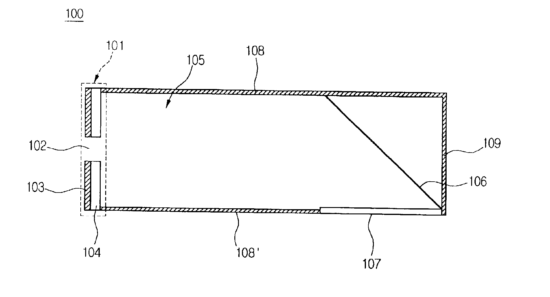
[0137]FIG. 12 is a schematic structure view illustrating an integrator engaged with a color wheel in accordance with the present invention.

[0138]Referring to FIG. 12, the integrator 140 includes an incident unit 141 for passing externally-inputted lights, and reflecting internally-inputted lights, a polarizing unit 145 for externally outputting polarized lights among the lights inputted to the incident unit 141, and a recycling unit 146 for recycling the lights inputted to the incident unit 141 within a certain space until they are externally outputted.

[0139]The incident unit 141 was explained with reference to FIGS. 5 and 6, and thus detailed explanations thereof are omitted.

[0140]The polarizing unit 145 serve to convert non-polarized lights inputted through an opening 142 into polarized lights. Any kinds of means having P / S splitting function such as a PBS or reflection type polarizing plate can be used as the polarizing unit. The polarizing unit is positioned to face the incident...

third embodiment

[0167]FIG. 18 is a schematic view illustrating a polarization conversion device in accordance with the present invention.

[0168]Referring to FIG. 18, the polarization conversion device 160 includes an integrator 140 for homogenizing externally-inputted heterogeneous lights by recycling, and polarizing and outputting the homogenized lights, a color bar filter 162 incorporated with the integrator 140, for splitting the polarized lights from the integrator 140 into R, G and B lights, and selectively transmitting the split lights, and a rotating prism 168 rotated for changing an alignment order of the color lights outputted from the color bar filter 162. Here, the integrator 140 includes an incident unit 141, a polarizing unit 145 and a recycling unit 146, identically to the integrator of FIG. 14.

[0169]The color bar filter 162 is fixedly adhered to the polarizing unit 145 of the integrator 140, and includes R, G and B transmitting filters 164, 165 and 166. Preferably, the R, G and B tran...


PUM


Abstract

An integrator and a display apparatus using the same simplify the structure of an optical system and minimize optical loss. The integrator homogenizes, polarizes and recaptures incident lights. The optical loss can be reduced by using a color drum and a color wheel engaged with the integrator. In order to minimize the optical loss, a polarization conversion device where a color bar filter or color switch is directly adhered to an integrator is used. The polarization conversion device can be applied to a projector for embodying small images into large ones.

Description

BACKGROUND OF THE INVENTION[0001]1. Field of the Invention[0002]The present invention relates to a display apparatus for displaying large-screen images, and more particularly to an integrator which can improve optical efficiency by simplifying the structure of an optical system and minimizing optical loss, and a polarization conversion device using the same.[0003]2. Background of the Related Art[0004]Recently, a plate-type display apparatus which is thin and suitable for large-screen images has attracted attention instead of a CRT (Cathode Ray Tube) which is restricted in screen size and which has a large-sized system. Exemplary plate-type display apparatuses include LCD (Liquid Crystal Display, PDP (Plasma Display Panel) and projector.[0005]Among the large-screen image display apparatuses, the projector displays color images by enlarging and projecting small images of a small-sized display device into a large screen through a projecting lens. It has been expected to replace the oth...

Claims


Application Information

Patent Timeline
IPC IPC(8): G03B21/00H04N9/31
CPCG03B21/00H04N9/3117H04N9/3197Y10S385/901G03B21/005
Inventor KANG, HO JOONG
Owner LG ELECTRONICS INC
Why Eureka
Try Eureka