CPP GMR free layer having ferromagnetic layers with parallel magnetization separated by non-magnetic layer

Inactive Publication Date: 2005-08-09
FUJITSU LTD
View PDF14 Cites 88 Cited by
  • Summary
  • Abstract
  • Description
  • Claims
  • Application Information

AI Technical Summary

Benefits of technology

[0019]A magnetoresistive device of another aspect of the present invention includes a laminated film, and a mechanism for applying sense current in a direction of lamination in the laminated film, wherein the laminated film includes a first ferromagnetic layer having a substantially fixed direction of magnetization, a second ferromagnetic layer having a freely variable direction of magnetization according to an external magnetic field, and a non-magnetic intermediate layer that separates the first and second ferromagnetic layer from each other, wherein one of the first and second ferromagnetic layers has a lamination of a non-magnetic part and a ferromagnetic part in a direction of lamination in said laminated film. Although this magnetoresistive device may increase a spin dependent scattering effect of a conduction electron and thus enhance the magnetoresistance change, the ferromagnetic layer may be the first ferromagnetic layer or a combination of the first and second ferromangnetic layers; it is also not limi

Problems solved by technology

This magnetoresistive device increases the number of interferences betwee

Method used


Image

  • CPP GMR free layer having ferromagnetic layers with parallel magnetization separated by non-magnetic layer
  • CPP GMR free layer having ferromagnetic layers with parallel magnetization separated by non-magnetic layer
  • CPP GMR free layer having ferromagnetic layers with parallel magnetization separated by non-magnetic layer

Examples


example 1

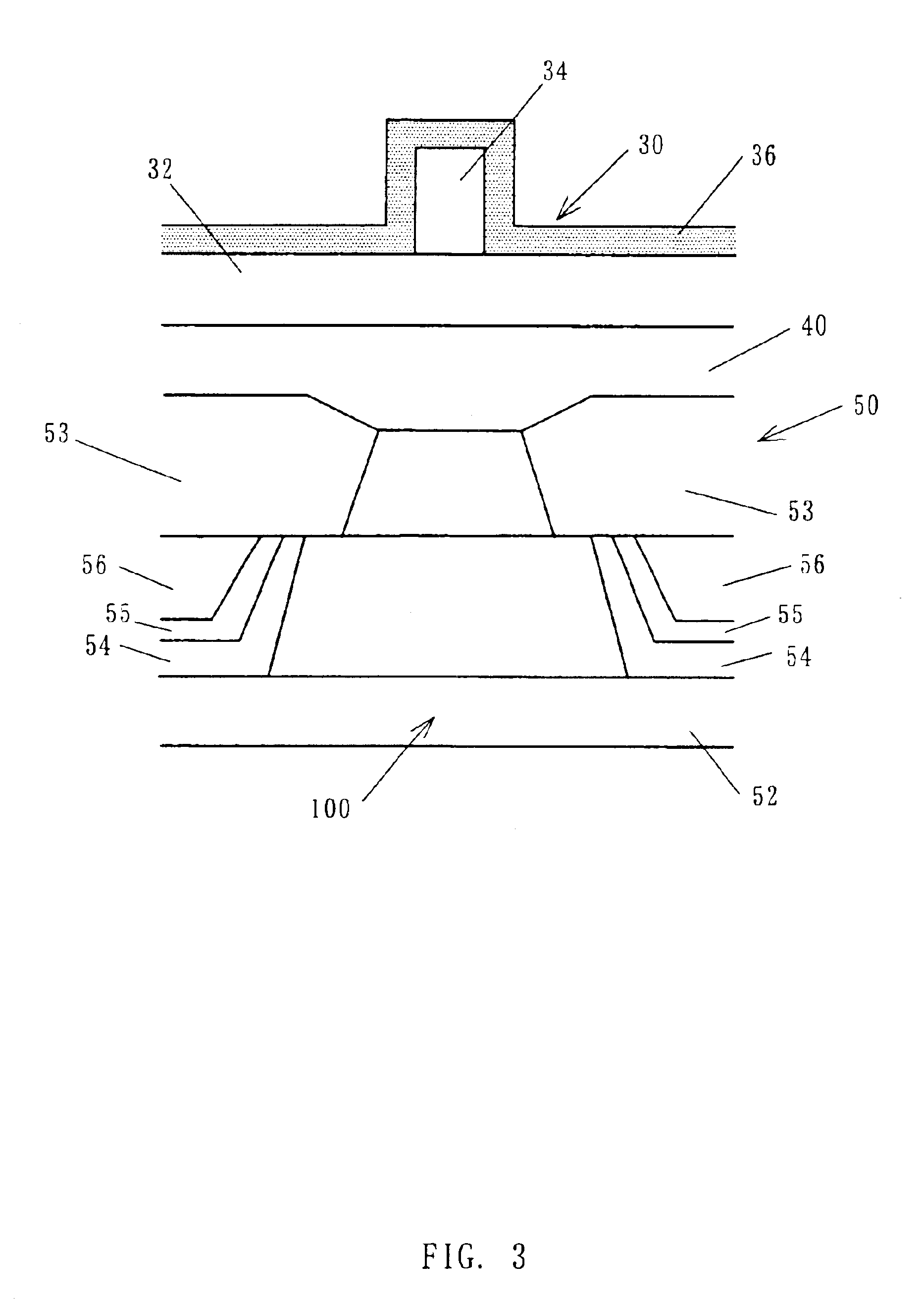
[0059]As shown in FIG. 5, there is formed a bottom spin-valve film 100 of a first embodiment according to the present invention. Here, FIG. 5 is an enlarged sectional view of the spin-valve film 100 applicable to a structure shown in FIG. 3. Laminated, in order from down to up, on the lower shield-lower electrode layer 52 are the primary coat layer 102 that includes the layer made of Ta with a layer thickness of 5 nm and the layer made of NiFe with a layer thickness of 2 nm, the exchange-coupling layer 104 made of PdPtMn with a layer thickness of 15 nm, the pinned ferromagnetic layer 106 made of CoFeB with a layer thickness of 3 nm, the non-magnetic intermediate layer 108 made of Cu with a layer thickness of 4 nm, a free ferromagnetic layer 120 with a layer thickness of 5 nm, and the electrode 110 that includes the layer made of Cu with a layer thickness of 1 nm, and the layer made of Au with a layer thickness of 10 nm.

[0060]The free ferromagnetic layer 120 includes a first free fer...

example 2

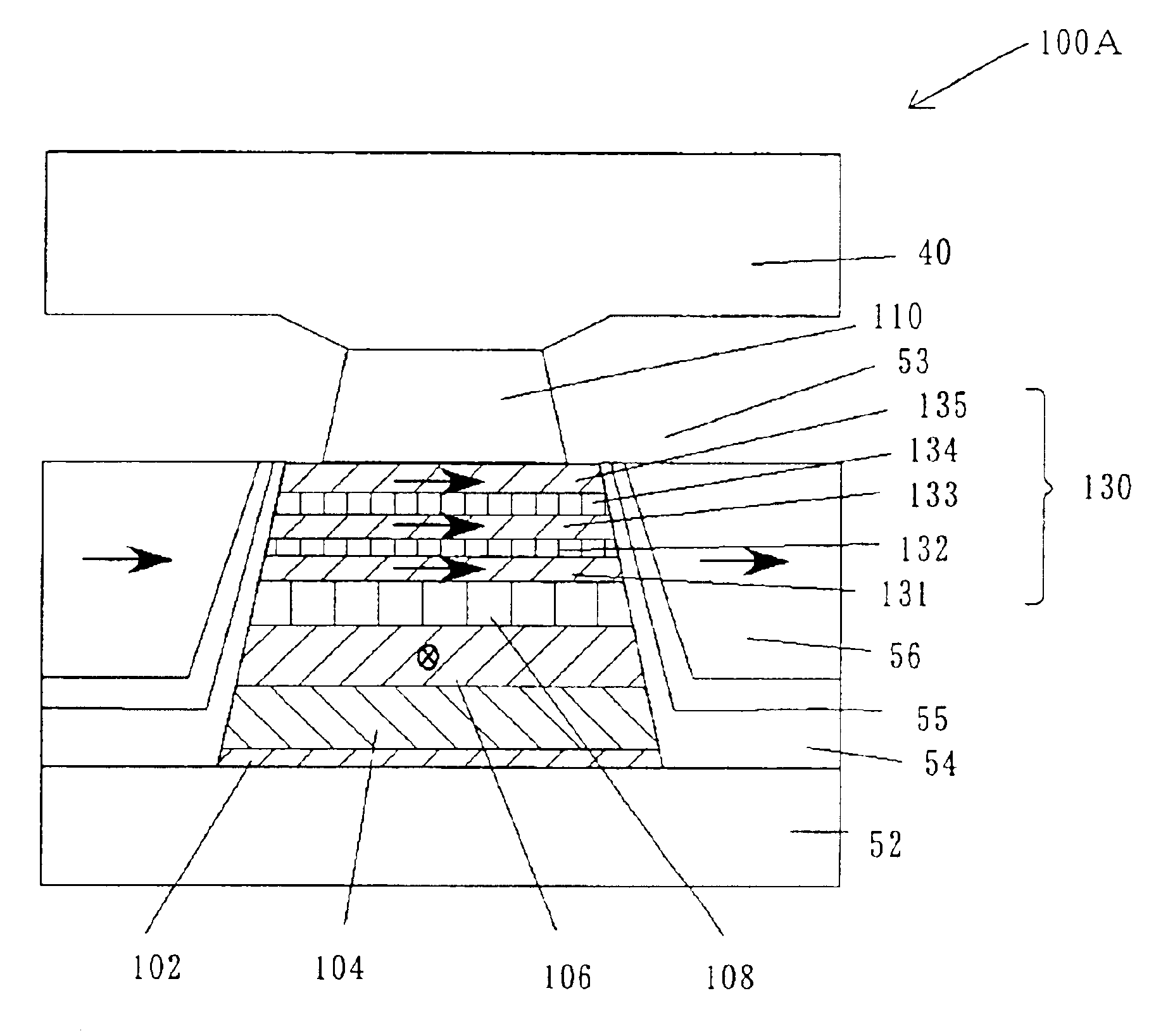
[0061]As shown in FIG. 6, there is formed a bottom spin-valve film 100A of a second embodiment according to the present invention. Here, FIG. 6 is an enlarged sectional view of the spin-valve film 100A applicable to a structure shown in FIG. 3. Laminated, in order from down to up, on the lower shield-lower electrode layer 52 are the primary coat layer 102 that includes the layer made of Ta with a layer thickness of 5 nm and the layer made of NiFe with a layer thickness of 2 nm, the exchange-coupling layer 104 made of PdPtMn with a layer thickness of 15 nm, the pinned ferromagnetic layer 106 made of CoFeB with a layer thickness of 3 nm, the non-magnetic intermediate layer 108 made of Cu with a layer thickness of 4 nm, a free ferromagnetic layer 130 with a layer thickness of 7 nm, and the electrode 110 that includes the layer made of Cu with a layer thickness of 1 nm, and the layer made of Au with a layer thickness of 10 nm.

[0062]The free ferromagnetic layer 130 includes a ferromagnet...

example 3

[0064]As shown in FIG. 7, there is formed a bottom spin-valve film 100B having a synthetic ferri structure of a third embodiment according to the present invention. Here, FIG. 7 is an enlarged sectional view of the spin-valve film 100B applicable to a structure shown in FIG. 3. Laminated, in order from down to up, on the lower shield-lower electrode layer 52 are the primary coat layer 102 that includes the layer made of Ta with a layer thickness of 5 nm and the layer made of NiFe with a layer thickness of 2 nm, the exchange-coupling layer 104 made of PdPtMn with a layer thickness of 15 nm, the pinned ferromagnetic layer 140 having the synthetic fern structure with a layer thickness of 7.8 nm, the non-magnetic intermediate layer 108 made of Cu with a layer thickness of 4 nm, the free ferromagnetic layer 120 with a layer thickness of 5 nm, and the electrode 110 that includes the layer made of Cu with a layer thickness of 1 nm, and the layer made of Au with a layer thickness of 10 nm.

[...


PUM


Abstract

A magnetoresistive device includes a laminated film, and a mechanism for applying sense current in a direction of lamination in the laminated film, wherein the laminated film includes a first ferromagnetic layer having a substantially fixed direction of magnetization, a second ferromagnetic layer having a freely variable direction of magnetization according to an external magnetic field, the second ferromagnetic layer including a non-magnetic metal layer, and two or more ferromagnetic metal layers separated from each other by the non-magnetic metal layer in the direction of lamination, and a non-magnetic intermediate layer that separates the first and second ferromagnetic layer from each other.

Description

BACKGROUND OF THE INVENTION[0001]The present invention relates generally to reproducing of a record carrier using magnetic means, and more particularly to a magnetoresistive device. The present invention is suitable, for example, for a read head for use with a hard disc drive (referred to as “HDD” hereinafter).[0002]Available electronic information content has explosively increased with the recent rapid technology development, as in the Internet. Accordingly, smaller and larger-capacity magnetic recorders, typified by HDDs, have been increasingly demanded to store such a large amount of information. A surface recording density indicative of recordable information content per unit recording area is required to be higher to realize a smaller and larger-capacity HDD.[0003]At present, the surface recording density improves at an annual rate of about 100%. The increased surface recording density accordingly reduces an area on a record carrier corresponding to one bit as a minimum unit of...

Claims


Application Information

Patent Timeline
IPC IPC(8): G11B5/00G11B5/012G11B5/39H01L43/08
CPCB82Y10/00B82Y25/00G11B5/00G11B5/012G11B5/3903H01L43/08G11B2005/3996H10N50/10G11B5/39
Inventor SHIMIZU, YUTAKAOSHIMA, HIROTAKANAGASAKA, KEIICHISEYAMA, YOSHIHIKOTANAKA, ATSUSHI
Owner FUJITSU LTD
Why Eureka
Try Eureka