Cooling structure for disk storage device

a technology for storage devices and cooling structures, applied in domestic cooling devices, electric apparatus casings/cabinets/drawers, instruments, etc., to achieve the effect of improving the degree of freedom of signal lines

Active Publication Date: 2005-08-09
GOOGLE LLC
View PDF17 Cites 166 Cited by
  • Summary
  • Abstract
  • Description
  • Claims
  • Application Information

AI Technical Summary

Benefits of technology

[0007]The invention has been accomplished in view of the foregoing problems, and an object is to provide a cooling structure for a disk storage device that cools effectively disk drives accommodated at a hi

Problems solved by technology

For this reason, it is unnecessary to form a flow path for letting cooling air flow therethrough within the d

Method used


Image

  • Cooling structure for disk storage device
  • Cooling structure for disk storage device
  • Cooling structure for disk storage device

Examples


first embodiment

[1. First Embodiment]

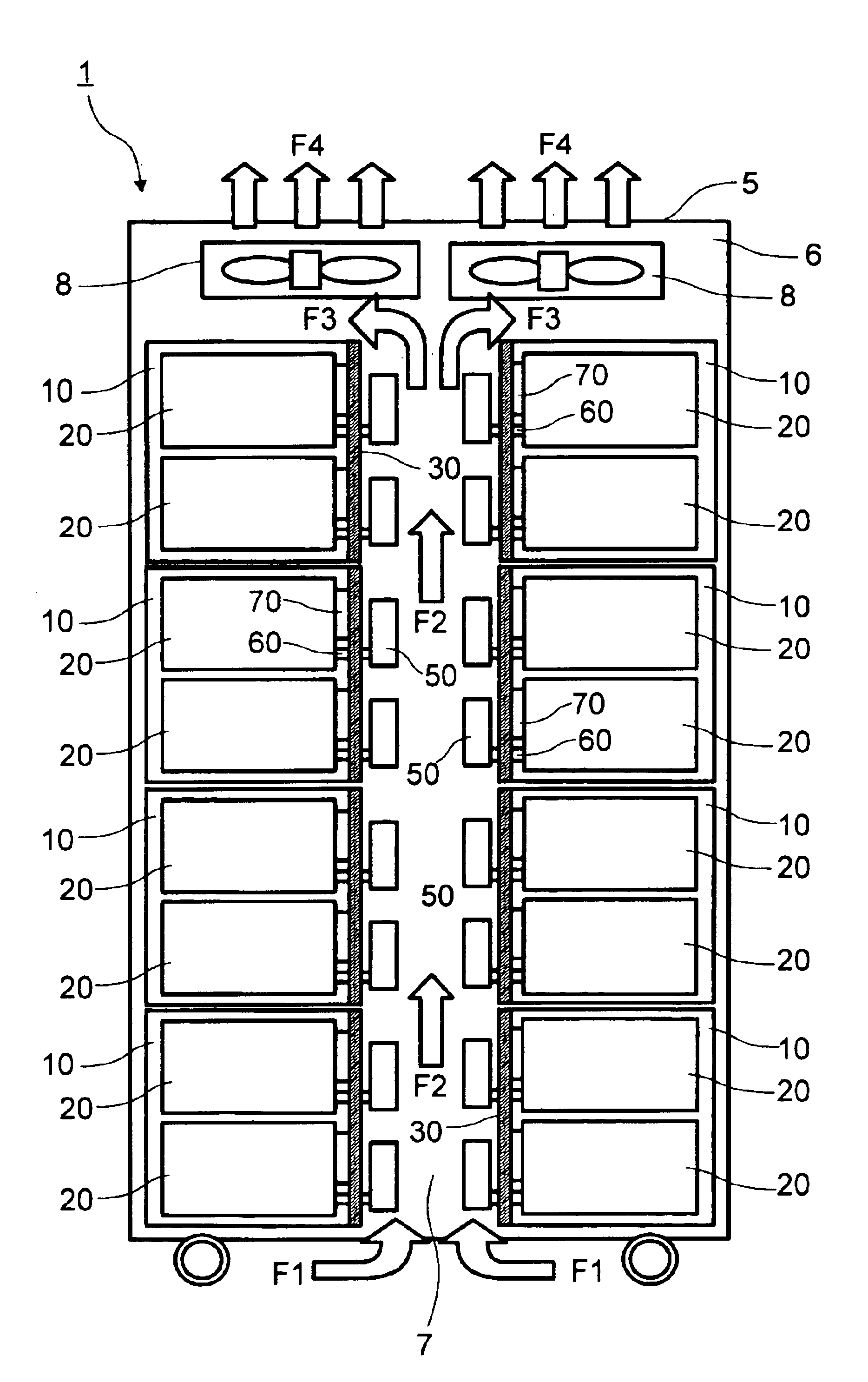
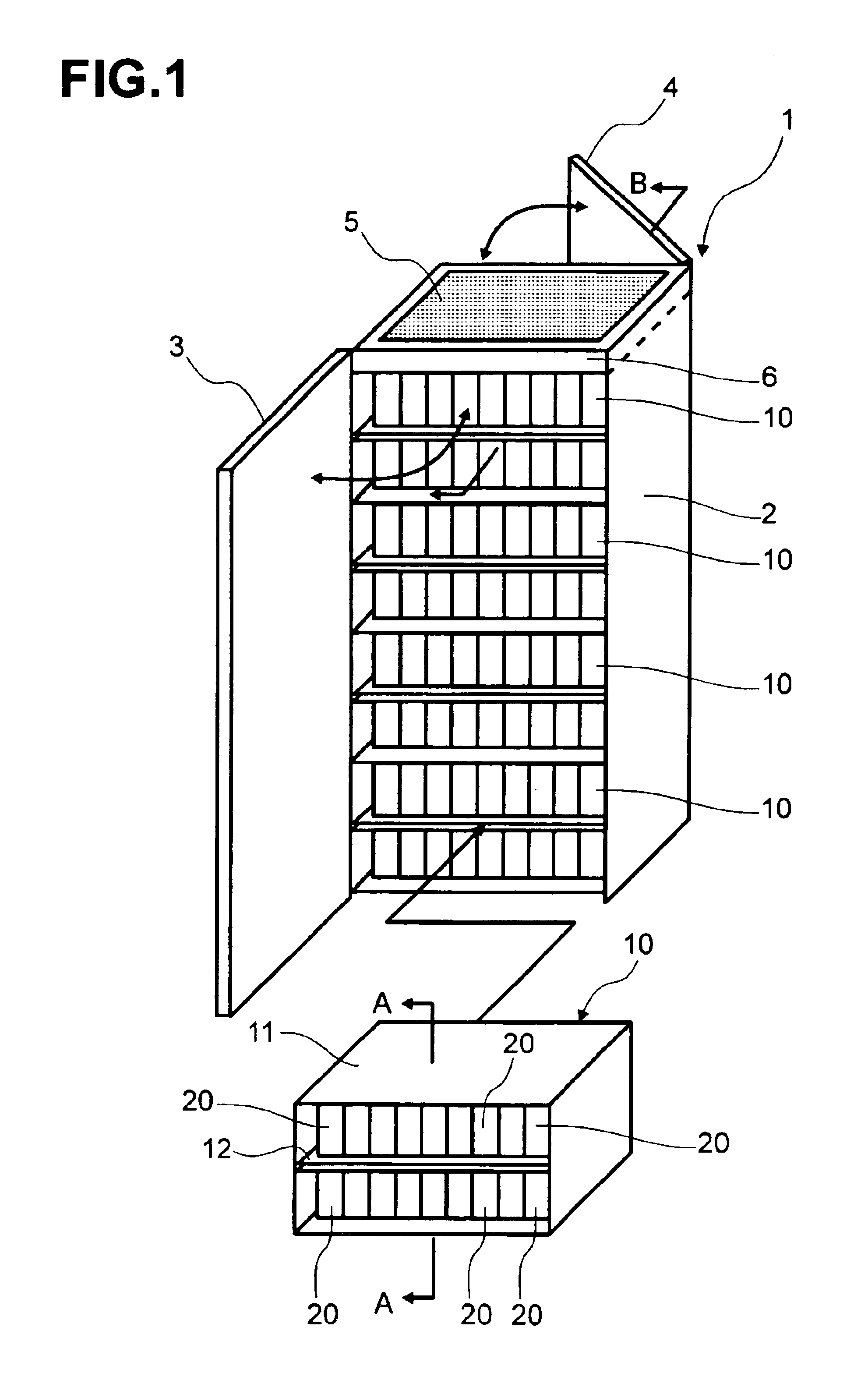
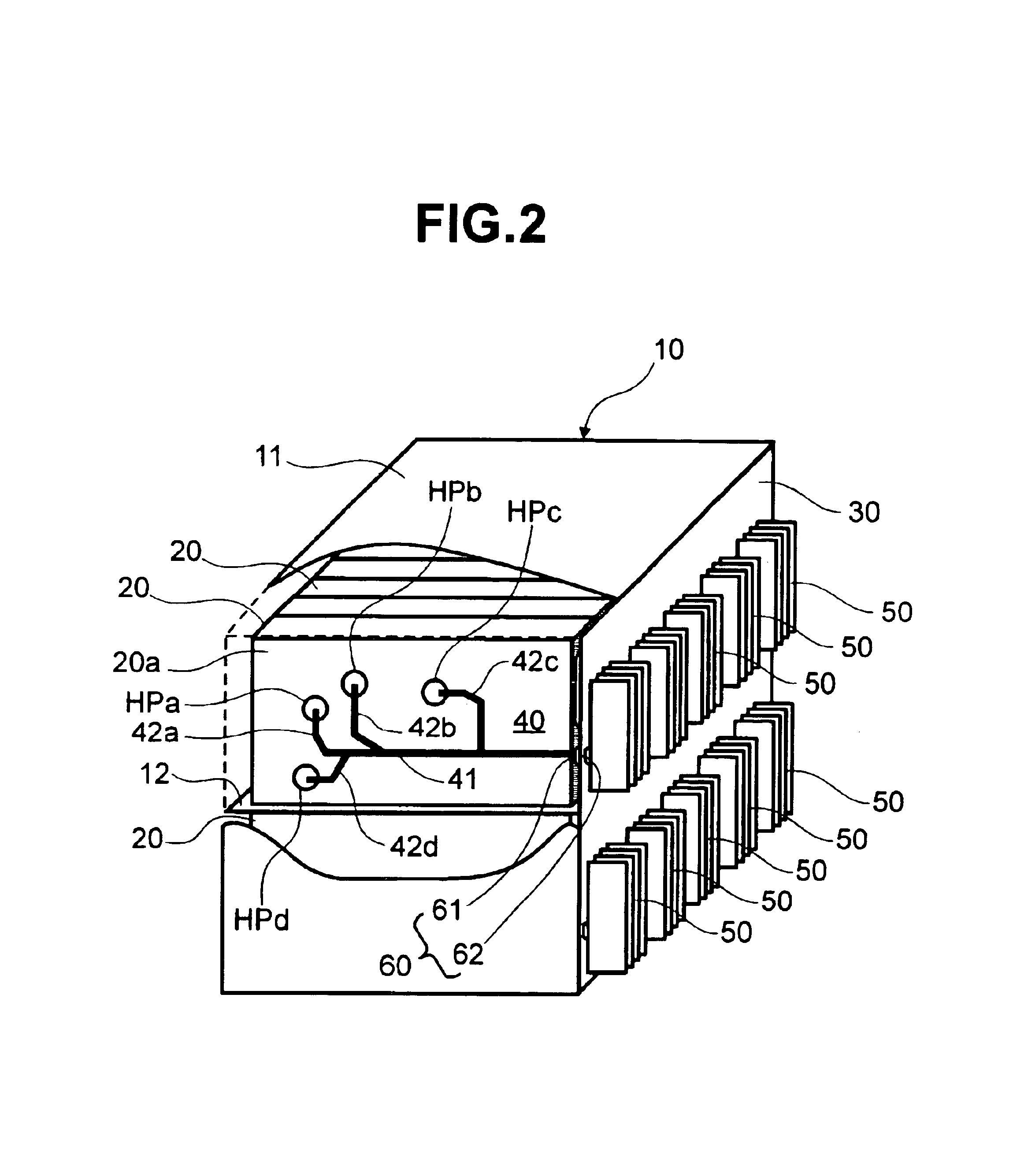
[0035]With reference to FIGS. 1 through 8, a first embodiment of the invention is described. FIG. 1 shows an exterior view showing the entirety of a disk array apparatus 1. The disk array apparatus 1 comprises a plurality of disk drive boxes (hereafter referred to as “box / boxes”) 10 stacked on top of each other in a rack 2. Although the details will be described later, each box 10 has a case 11 that is partitioned into two compartments separated vertically, with a control board 12 defining their boundary, and each of the compartments detachably / reattachably accommodates a plurality of disk drives 20 that are substantially in close contact with each other.

[0036]The front and rear of the rack 2 are opened, and a front door 3 and a back door 4, which are openable / closable, are provided respectively for the front opening and the rear opening. Within the rack 2, a plurality of the boxes 10 are accommodated detachably / reattachably, and in each of the front part and re...

second embodiment

[2. Second Embodiment]

[0057]Next, a second embodiment of the invention is described with reference to FIG. 11. A feature of the present embodiment is that the heat radiated from the boxes 10 is cooled by a liquid cooling system. FIG. 11 is a schematic cross-sectional view of a disk array apparatus 100 according to the present embodiment. The configurations of the boxes 10, the disk drives 20, and so forth are similar to those of the foregoing embodiment, and therefore the description is omitted. In the present embodiment, a liquid-cooling system cooling machine room 110 is provided in a lower portion of a rack 101, and a cooling pipe 120 in which refrigerant circulates is laid inside a space 102 that is defined in the rack 101, with the space 102 extending vertically. The heat connectors 60 of the disk drives 20 (more accurately, the heat-dissipating-side heat connectors 62) are respectively connected to the cooling pipe 120 so that they can conduct heat. That is, the present embodi...

third embodiment

[3. Third Embodiment]

[0060]Next, a third embodiment of the invention is described with reference to FIG. 12. A feature of the present embodiment is that the shape of the heat-absorbing part is changed. For example, as illustrated in the upper portion of FIG. 12, a heat-absorbing part 200 may be formed into a flat plate shape that covers a side face of a disk drive 20. Alternatively, as illustrated in the lower portion of FIG. 12, a heat-absorbing part 210 may be formed in a network-like shape that covers a side face of a disk drive 20.


PUM


Abstract

A disk drive box 10 accommodates a plurality of disk drives 20 within a case 11. A side face of each of the drives 20 is provided with a heat-absorbing part 40 including a heat pipe, corresponding to heat producing area HP. The heat taken away by the heat-absorbing part 40 is transmitted to a heat sink 50 of the rear of a backboard 30 via a heat connector 60. The heat sink 50 is cooled by cooling air flowing through an air duct 7. By cooling the drive 20 with the heat pipe, clearances between the drives 20 can be substantially eliminated, and it is made unnecessary to form an opening for air cooling in the backboard 30. Thus, size reduction is possible, and it is possible to increase the degree of freedom for a wiring pattern formed on the backboard 30.

Description

CROSS REFERENCE TO RELATED APPLICATION[0001]This application relates to and claims priority from Japanese Patent Application No. 2003-183988, filed on Jun. 27, 2003, the entire disclosure of which is incorporated herein by reference.FIELD OF THE INVENTION[0002]The present invention relates, for example, to a structure for cooling a disk storage device in which a plurality of disk drives are accommodated.BACKGROUND OF THE INVENTION[0003]A disk array apparatus for storing a large amount of data comprises a multiplicity of disk storage devices and the like connected with each other and provides, for example, a storage area in accordance with RAID (Redundant Array of Independent Inexpensive Disks). Each of disk storage devices comprises, for example, a plurality of disk drives, such as hard disk drives. The plurality of disk drives are mounted side by side and attached onto an electric circuit board for connection, called a “backboard.” Because the disk drives generate heat while they a...

Claims


Application Information

Patent Timeline
IPC IPC(8): G11B33/14H05K7/20
CPCG11B33/142H05K7/20736H05K7/20809
Inventor FUKUDA, HIROSHIFUJITA, KENJI
Owner GOOGLE LLC
Why Eureka
Try Eureka