Methods and apparatus for reclaiming components of concrete and other slurries

a technology of concrete and components, applied in the direction of chemistry apparatus and processes, mixers, mixing, etc., can solve the problems of concrete manufacturers' economic pressure, mix cannot remain, and the problem of disposal

Inactive Publication Date: 2005-08-16
METZ JEFFREY LEE
View PDF25 Cites 14 Cited by
  • Summary
  • Abstract
  • Description
  • Claims
  • Application Information

AI Technical Summary

Benefits of technology

[0010]In similar fashion, any plant line supplying process water from the batch supply vessel to the concrete batch mixing plant may include a recycling line extending therefrom and returning back to the batch supply vessel, whereby any contents of the batch supply vessel traveling through the plant line may be at least partially returned to the batch supply vessel to maintain...

Problems solved by technology

The popularity of concrete is continuously growing in the field of building materials, but so are environmental and economic pressures on concrete manufacturers, i.e., the producers of “ready-mix” concrete.
Trucks often return to the plant and unused mix, leading to disposal issues.
The mix cannot remain in the trucks for later use, or it will harden and render the trucks unusable.
If the mix is merely dumped, it will generate long-term space issues since it will be difficult to remove later.
Additionally, dumping generates environmental issues because stormwater and other runoff can wash out components of the mix and cause groundwater contamination.
Dumping is also wasteful because high-quality concrete is expensive, and it woul...

Method used


Image

  • Methods and apparatus for reclaiming components of concrete and other slurries
  • Methods and apparatus for reclaiming components of concrete and other slurries

Examples


Embodiment Construction

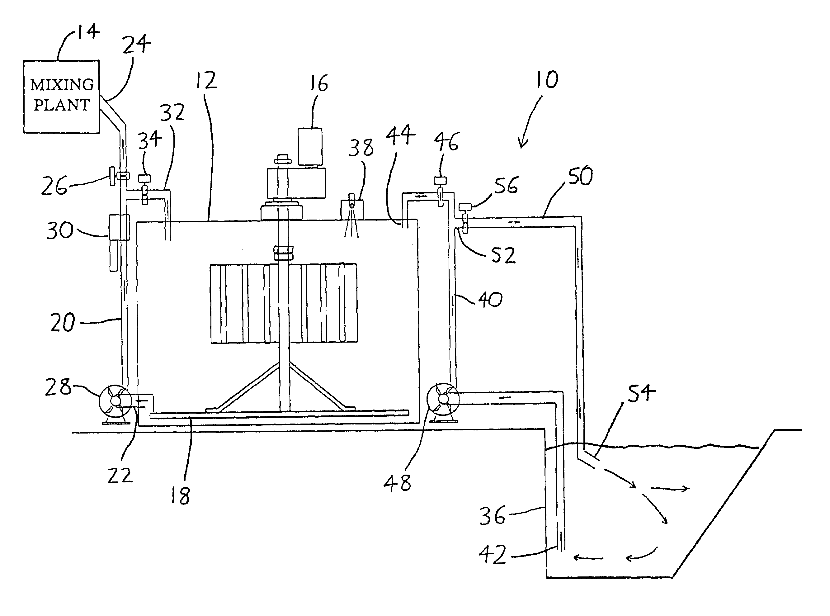
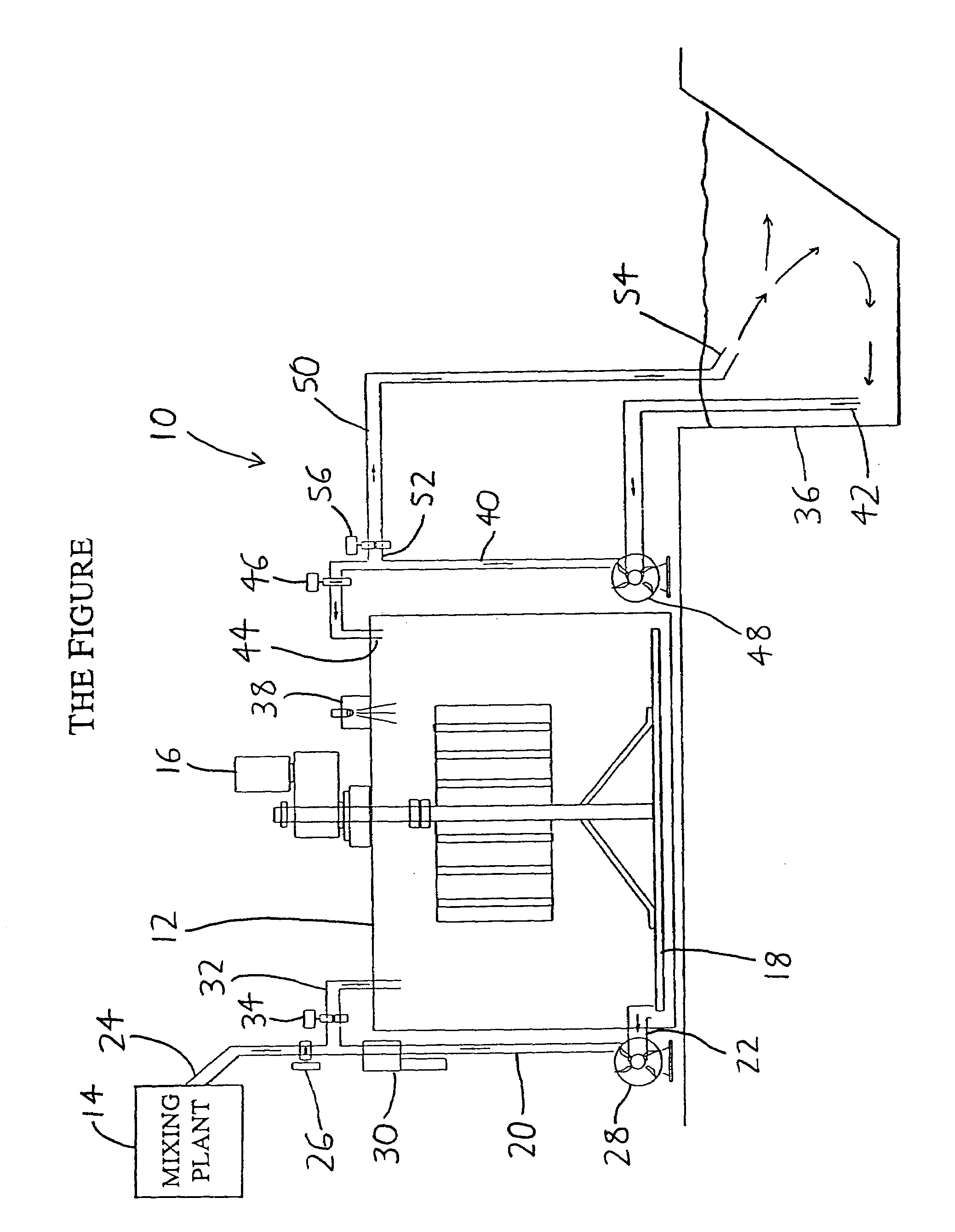
[0013]An exemplary version of the invention will now be described with reference to the accompanying FIGURE, wherein a reclamation system is generally designated by the reference numeral 10. A slurry batch supply vessel, depicted at the reference numeral 12, is intended to provide process water on an as-needed basis to a concrete branch mixing plant (depicted schematically at 22) for use in preparing new batches of ready-mix concrete. The batch supply vessel 12 may be provided by the pin present in a common ready-mix aggregate reclamation system, that is, the batch supply vessel 12 can be the bin used to contain residue recovered after fluid concrete (unset concrete) has undergone processes to remove solids ranging from aggregate size down to approximately sand size. Thus, the batch supply vessel 12 will generally contain water and concrete components obtained after removal of particulates (aggregates, cobbles, etc.) down to approximately the sieve size of sand.

[0014]In practice, th...


PUM


Abstract

A reclamation system for the recycling of components of fluid concrete (such as concrete fines) and for concrete plant wastewater includes a slurry batch supply vessel which meters process water to a concrete batch mixing plant for use in concrete production processes, and a slurry retention vessel which collects stormwater, concrete truck washout, and other plant waste and wastewater for supply to the batch supply vessel when needed. The retention vessel, which may be no more than a waste pit, includes a fluid supply circuit which supplies water and suspended solids to the batch supply vessel, and a recirculation circuit which collects water and suspended solids from the retention vessel (or from the supply circuit) and reinjects the collected water and solids back into the retention vessel to agitate settled solids back into suspensions (so that they may be taken up by the supply circuit). As a result, the retention vessel will empty itself of accumulated water and waste solids and supply them (via the batch supply vessel) to the concrete batch mixing plant for recycling, rather than requiring the cost and inconvenient of periodic manual emptying.

Description

FIELD OF THE INVENTION[0001]The disclosure concerns an invention relating generally to methods and apparatus for recycling components of slurries, in particular methods and apparata for separation, recovery, and / or reuse of components of fluid concrete (pourable, unset concrete).BACKGROUND OF THE INVENTION[0002]The popularity of concrete is continuously growing in the field of building materials, but so are environmental and economic pressures on concrete manufacturers, i.e., the producers of “ready-mix” concrete. Fluid (unset) concrete—including aggregate, sand, possibly industrial byproducts (such as fly ash), portland cement and water—is mixed in batchers at the concrete plant and hauled in concrete trucks to the construction site, where the fluid concrete mix is poured to set. Trucks often return to the plant and unused mix, leading to disposal issues. The mix cannot remain in the trucks for later use, or it will harden and render the trucks unusable. If the mix is merely dumped...

Claims


Application Information

Patent Timeline
IPC IPC(8): B01F15/02B01F27/91
CPCB01F7/22B01F15/0203B01F7/0015B01F2215/0047B01F27/0725B01F27/91B01F35/712B01F2101/28
Inventor METZ, JEFFREY LEE
Owner METZ JEFFREY LEE
Why Eureka
Try Eureka