Method and apparatus for LWD shear velocity measurement

a technology of shear velocity and method, which is applied in the direction of instruments, surveying, and well accessories, etc., can solve the problems of not being able to directly measure shear velocity from monopole logging, the technology has not yet been commercially applied in the oil and gas industry, and the refract is no longer refractibl

Inactive Publication Date: 2005-08-16
BAKER HUGHES INC
View PDF24 Cites 75 Cited by
  • Summary
  • Abstract
  • Description
  • Claims
  • Application Information

AI Technical Summary

Benefits of technology

[0015]When the formation is azimuthally anisotropic, the quadrupole array data is responsive primarily to the slow shear wave velocity. For such an azimuthally anisotropic formation, in an optional embodiment of the invention, cross-dipole (4C) shear data are also be obtained. During rotation of the logging tool in a logging while drilling environment, orientation sensors on the tool are used to monitor the toolface angle. Using the measured toolface angle, the cross-dipole data are rotated to a fixed coordinate system. Prior art methods are used to determine the principal direction of azimuthal anisotropy from the cross-dipole data in the fixed coordinate system. The cross-dipole data are then rotated to the principal directions. Subsequent processing of the quadrupole data and the cross-dipole data in the principal direction using a weighted spectral averaging makes it possible to recover the magnitude of the azimutal anisotropy of the formation.

Problems solved by technology

A formation that has a shear wave velocity faster than the borehole fluid is called a ‘fast formation.’ However, in a formation where the shear velocity is slower than borehole fluid velocity, a ‘slow formation,’ the shear wave can no longer refract along the borehole wall, and the shear velocity cannot be directly measured from monopole logging.
), this technology has not yet been commercially applied to the oil and gas industry.
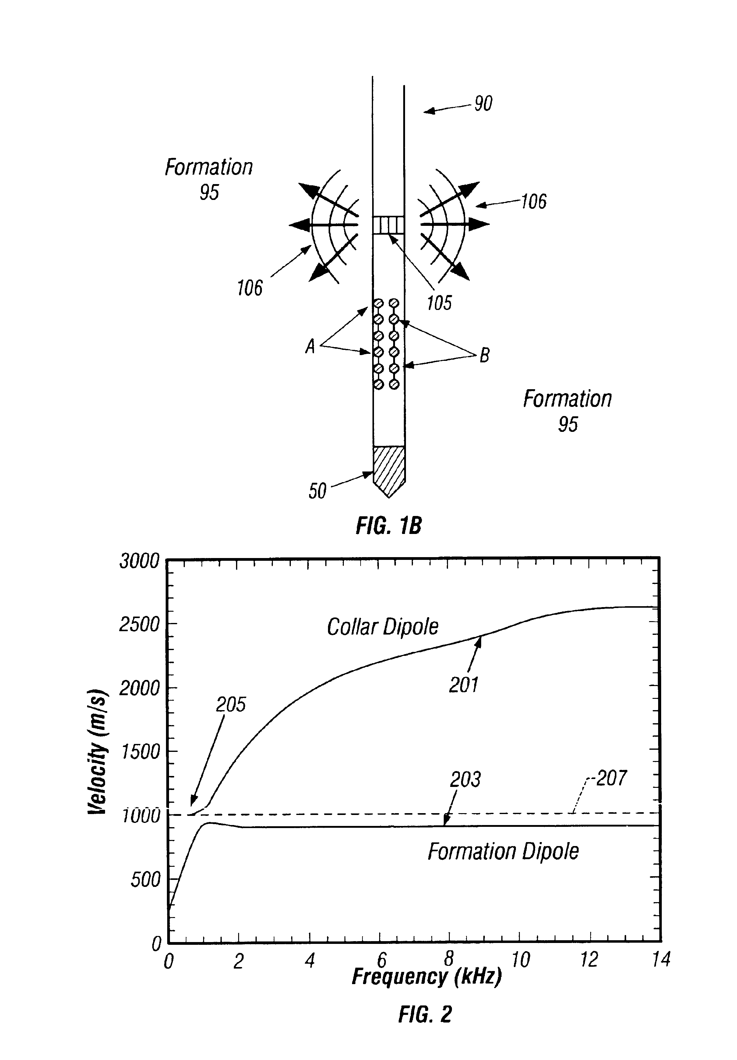
The application of the dipole acoustic technology to LWD has a serious drawback caused by the presence of the drilling collar with BHA that occupies a large part of the borehole.
The drawback is that the formation dipole shear wave traveling along the borehole is severely contaminated by the dipole wave traveling in the collar.
The LWD quadrupole waves, however, can be quite dispersive.
The LWD 4C dipole measurement, however, has two important issues that must be solved.
The first is that the LWD dipole, as discussed above, does not directly measure formation shear velocity because of the drill-collar interference.
The second is that the rotation of the tool during drilling obscures the directionality of the dipole measurement.

Method used


Image

  • Method and apparatus for LWD shear velocity measurement
  • Method and apparatus for LWD shear velocity measurement
  • Method and apparatus for LWD shear velocity measurement

Examples


Embodiment Construction

[0042]The present invention is a method, system and apparatus for measuring shear wave formation velocities while a well is being drilled. To the extent that the following description is specific to a particular embodiment or a particular use of the invention, this is intended to be illustrative and is not to be construed as limiting the scope of the invention.

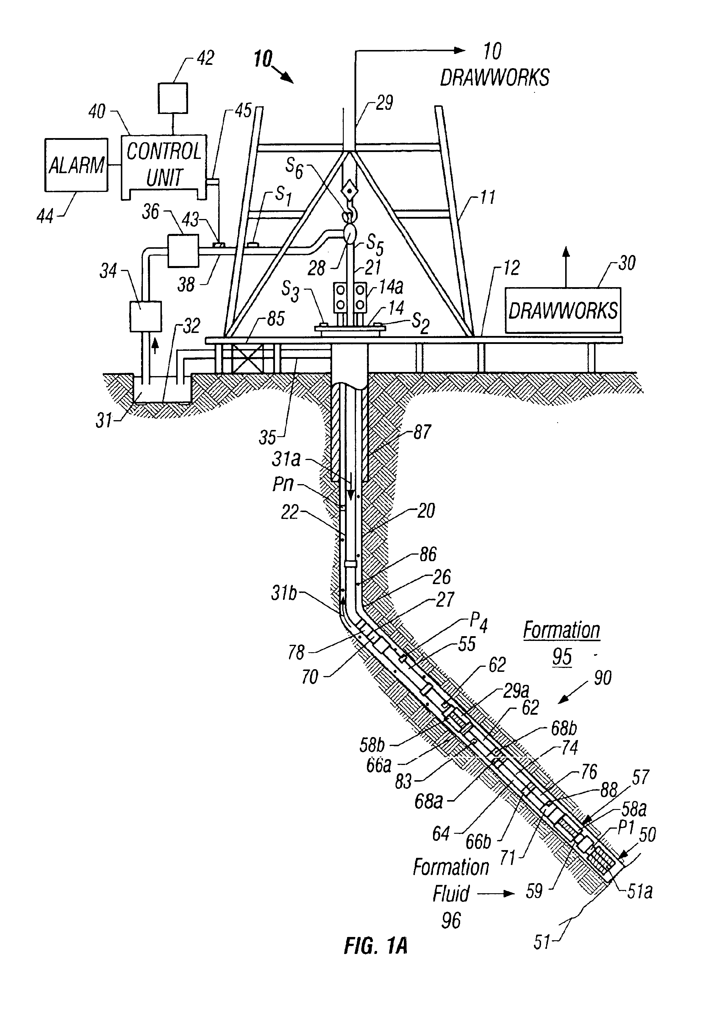
[0043]FIG. 1A shows a schematic diagram of a drilling system 10 having a bottom hole assembly (BHA) or drilling assembly 90 that includes sensors for downhole wellbore condition and location measurements. The BHA 90 is conveyed in a borehole 26. The drilling system 10 includes a conventional derrick 11 erected on a floor 12 which supports a rotary table 14 that is rotated by a prime mover such as an electric motor (not shown) at a desired rotational speed. The drill string 20 includes a tubing (drill pipe or coiled-tubing) 22 extending downward from the surface into the borehole 26. A drill bit 50, attached to the drill string...


PUM


Abstract

Array quadrupole data obtained in a LWD environment are processed to determine the shear velocity of an earth formation taking into account dispersion effects caused by the logging tool. When this processing is done in an azimuthally anisotropic formation, the shear velocity that is obtained is the slow shear velocity. When 4C (cross-dipole) data are also obtained, then both the fast and slow shear velocities of an azimuthally anisotropic formation can be obtained.

Description

CROSS REFERENCES TO RELATED APPLICATIONS[0001]This application is a continuation in part of U.S. patent application Ser. No. 10 / 045,263 filed on Nov. 7, 2001, now U.S. Pat. No. 6,850,168 with a priority claim to U.S. Provisional Patent Application Ser. No. 60 / 248,097 filed on Nov. 13, 2000. This application also claims priority from U.S. Provisional Patent Application Ser. No. 60 / 438,932 filed on Jan. 9, 2003 and from U.S. Provisional Application Ser. No. 60 / 462,358 filed on Apr. 11, 2003.FIELD OF THE INVENTION[0002]This invention generally relates to a method and apparatus for measuring and processing a characteristic of subsurface earth formations penetrated by a borehole. More specifically this invention relates to a method and apparatus for measuring and processing an acoustic characteristic such as formation shear wave velocity of subsurface sonic waves after these waves traverse earth formations adjoining a borehole or passing through a portion of the subsurface.BACKGROUND OF ...

Claims


Application Information

Patent Timeline
Patent Type & Authority Patents(United States)
IPC IPC(8): G01V1/48G01V1/44G01V1/40
CPCG01V1/44G01V1/48
Inventor TANG, XIAO MINGWANG, TSILIPATTERSON, DOUGLAS J.LEGGETT, III, JAMES V.DUBINSKY, VLADIMIR
Owner BAKER HUGHES INC
Why Eureka
Try Eureka