
Semiconductor laser driving apparatus with filter to attenuate enhanced frequency component and optical disk apparatus including the same

a technology of enhanced frequency and driving apparatus, which is applied in the direction of digital signal error detection/correction, instruments, television systems, etc., can solve the problems of uniform shape of recording marks recorded on optical discs, and recording marks generate the following inconveniences, etc., to achieve stable recording characteristics, high signal-to-ratio, and high density recording

Inactive Publication Date: 2005-08-16
PANASONIC CORP
View PDF13 Cites 11 Cited by
  • Summary
  • Abstract
  • Description
  • Claims
  • Application Information

AI Technical Summary

Benefits of technology

[0076]In one embodiment of the invention, the switching section causes the filter to operate so that the enhanced high frequency component included in the recording current is superposed on an entirety of at least one of the plurality of multi-pulses included in the pulse.
[0080]In one embodiment of the invention, the switching section causes the filter to operate so that the enhanced high frequency component included in the high frequency current is superposed on the reproduction current at the time of reproduction, and causes the filter to operate so that the enhanced high frequency component included in the recording current is attenuated at the time of recording.
[0094]Thus, the invention described herein makes possible the advantages of providing a semiconductor laser driving apparatus for providing stable recording characteristics at the time of high density recording and a reproduction current having a high signal-to-ratio, and an optical disc apparatus including such a semiconductor laser driving apparatus as a result of solving the above-described problems.

Problems solved by technology

Problem 1: The shape of the recording marks recorded on the optical disc is not uniform due to dispersion in the composition of the recording layer of the optical disc.
Problem 2: The shape of the recording marks recorded on the optical disc is not uniform due to fluctuations in linear velocity of tracks of the optical disc with respect to the optical pickup occurring during recording.
Problem 4: A high frequency signal superposed on the reproduction signal generates unnecessary radiation of high frequency noise to the outside of the semiconductor laser is driving apparatus.
In the case of the PWM system, by contrast, tapering of the recording mark generates the following inconvenience.
As a result, an error rate of the reproduction signal is raised.
Thus, an error rate of the reproduction signal is increased.
When the pulse width W2 is shorter, the temperature of the recorded 3T mark itself does not reach a thermal saturation point, As a result, the recorded 3T mark is unstable is terms of shape.
However, when a high frequency current of 300 MHz having an amplitude of 50 mApp is transmitted, a loss in the amplitude is generated during the transmission, as a result of which the high frequency current has a smaller amplitude when being input to the semiconductor laser.
However, this increases unnecessary radiation of high frequency noise to the outside of the semiconductor laser driving apparatus, which is a problem with respect to safety standards.
Therefore, it is impossible to provide a recording mark having proper recording characteristics.
However, due to restrictions on circuit design or the like, it is very difficult to provide the current driving section 511 with a frequency characteristic which is flat from a low frequency to a high frequency of 300 MHz.

Method used


Image

  • Semiconductor laser driving apparatus with filter to attenuate enhanced frequency component and optical disk apparatus including the same
  • Semiconductor laser driving apparatus with filter to attenuate enhanced frequency component and optical disk apparatus including the same
  • Semiconductor laser driving apparatus with filter to attenuate enhanced frequency component and optical disk apparatus including the same

Examples


Embodiment Construction

[0119]Hereinafter, the present invention will be described by way of illustrative examples with reference to the accompanying drawings.

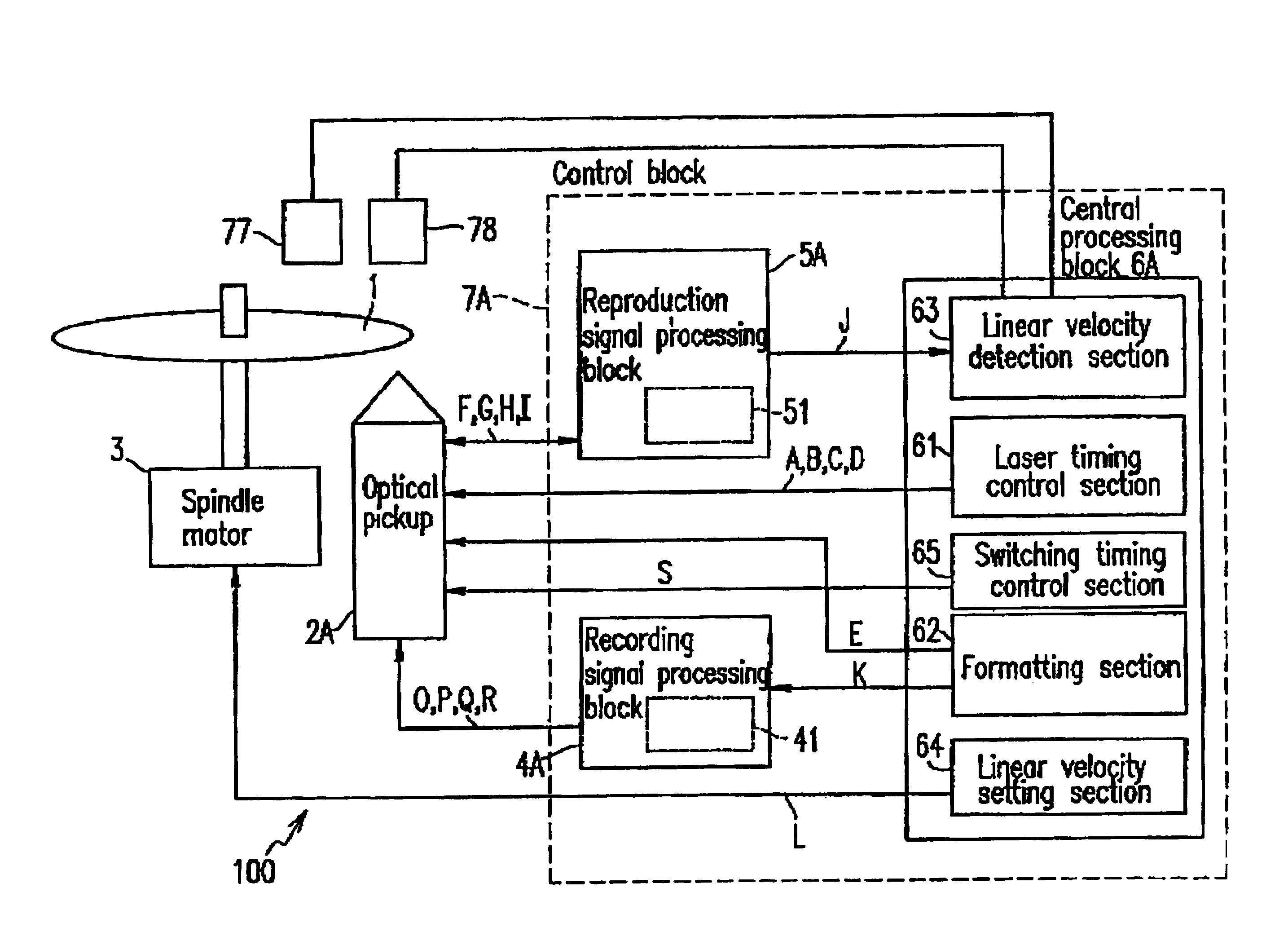
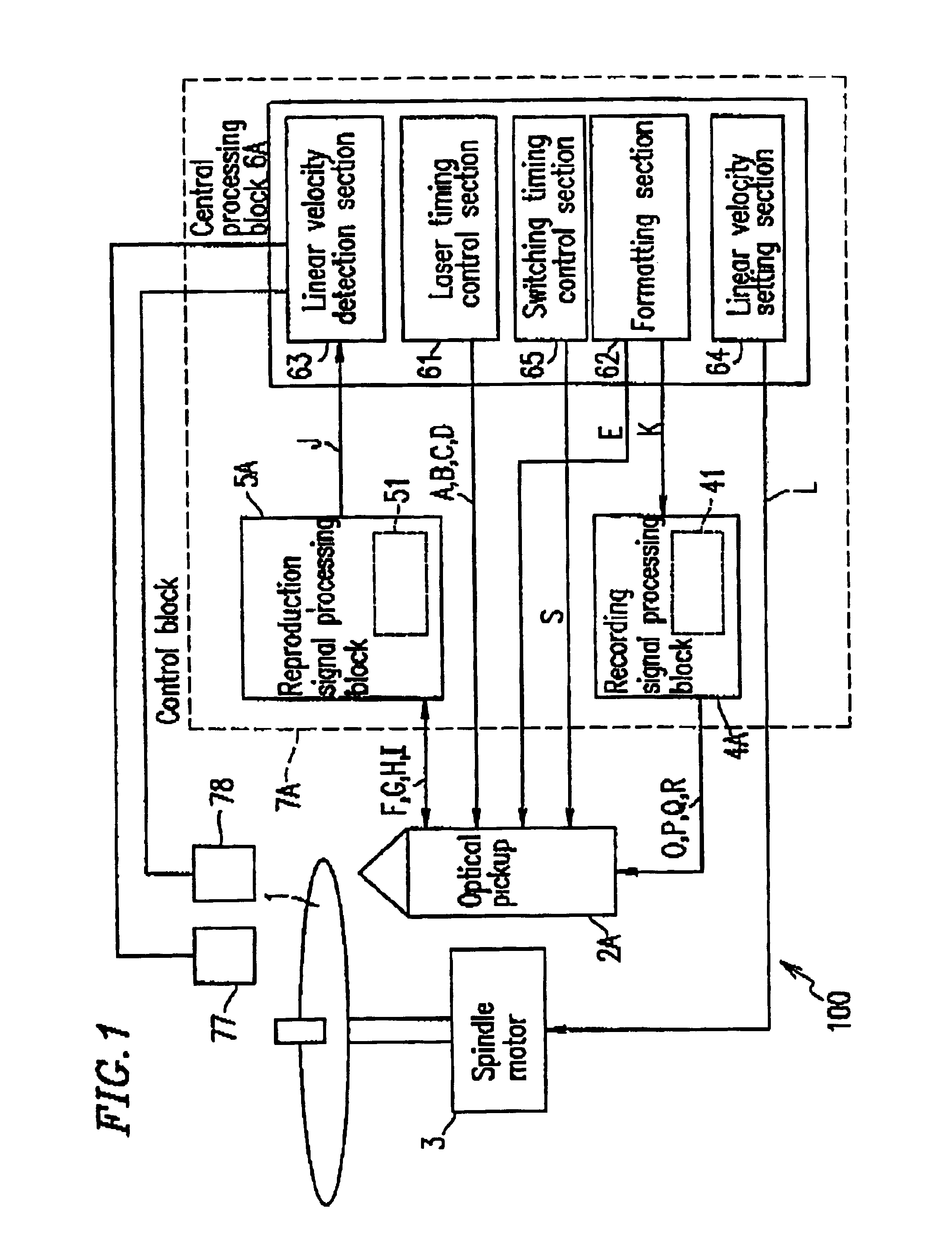
[0120]FIG. 1 is a schematic diagram illustrating a structure of an optical disc apparatus 100 according to an example of the present invention. Identical elements previously discussed with respect to FIG. 15 bear identical reference numerals and the detailed descriptions thereof will be omitted.

[0121]The optical disc apparatus 100 includes a spindle motor 3 for rotating an optical disc 1, an optical pickup 2A for recording a recording mark on the optical disc 1 or reproducing the recording mark recorded on the optical disc 1, and a control block 7A for controlling the optical pickup 2A and the motor 3. The control block 7A includes a recording signal processing block 4A, a reproduction signal processing block 5A, and a central processing block 6A. The central processing block 6A includes a linear velocity detection section 63, a laser timing control ...


PUM


Abstract

A semiconductor laser driving apparatus for directing light to an optical disc for recording a recording mark based on a recording current and reproducing the recording mark to generate a reproduction signal. The apparatus includes a reproduction current generation section; a high frequency current generation section for generating a current including a high frequency component for reducing semiconductor laser noise in the reproduction; a recording current generation section, the recording current including a pulse corresponding to the recording mark and including a plurality of multi-pulses; and a current driving section for amplification. The apparatus further includes a filter to attenuate the enhanced high frequency components in the high frequency current and in the enhanced high frequency component; and a switching section for switching the filter so that the enhanced component in the recording current is superposed on at least one of the multi-pulses.

Description

BACKGROUND OF THE INVENTION[0001]1. Field of the Invention[0002]The present invention relates to a semiconductor laser driving apparatus used for recording and reproducing data in an optical disc apparatus, and an optical disc apparatus including the same.[0003]2. Description of the Related Art[0004]Recently, an optical disc is expected to be used as a recording medium of video data replacing video tapes, in addition to an external recording medium for a personal computer. Video data encompasses an enormous amount of data. A high recording density is needed to record such an enormous amount of data on a small-diameter optical disc. The following is available as means for achieving a high recording density.[0005]Means 1: introduction of a PWM (pulse width modulation) system, by which information its recorded as the positions of edges of recording marks.[0006]Means 2: introduction of recording correction technology for correcting positions of edges of recording marks so as to reduce a...

Claims


Application Information

Patent Timeline
IPC IPC(8): H01S5/042H01S5/00G11B7/0045G11B7/005G11B7/00H01S5/068
CPCH01S5/042G11B7/00454G11B7/005H01S5/0427H01S5/06817
Inventor KAMIOKA, YUICHIAKAGI, TOSHIYAMIYABATA, YOSHIYUKITAKAHASHI, YUICHI
Owner PANASONIC CORP
Learn More