Hydraulic four-wheel driving apparatus

Inactive Publication Date: 2005-08-23
KANZAKI KOKYUKOKI MFG
View PDF7 Cites 32 Cited by
  • Summary
  • Abstract
  • Description
  • Claims
  • Application Information

AI Technical Summary

Benefits of technology

[0016]When steering for either left or right turning of the vehicle (when a steering wheel is rotated either right or left from its straight traveling position), operational load is applied on only one of the control arms linked to the respective steerable second drive wheels. Therefore,

Problems solved by technology

However, in the conventional front-wheel speed-increasing system, the hydraulic motor for driving the (steerable) front wheels is placed adjacent to the front wheels, thereby lengthening piping for connecting the hydraulic motor for driving the front wheels, to a hydraulic pump disposed in a transmission casing supporting the (unsteerable) rear wheels.
Since a front axle casing for driving the front wheels is extended laterally to be ver

Method used


Image

  • Hydraulic four-wheel driving apparatus
  • Hydraulic four-wheel driving apparatus
  • Hydraulic four-wheel driving apparatus

Examples


Example

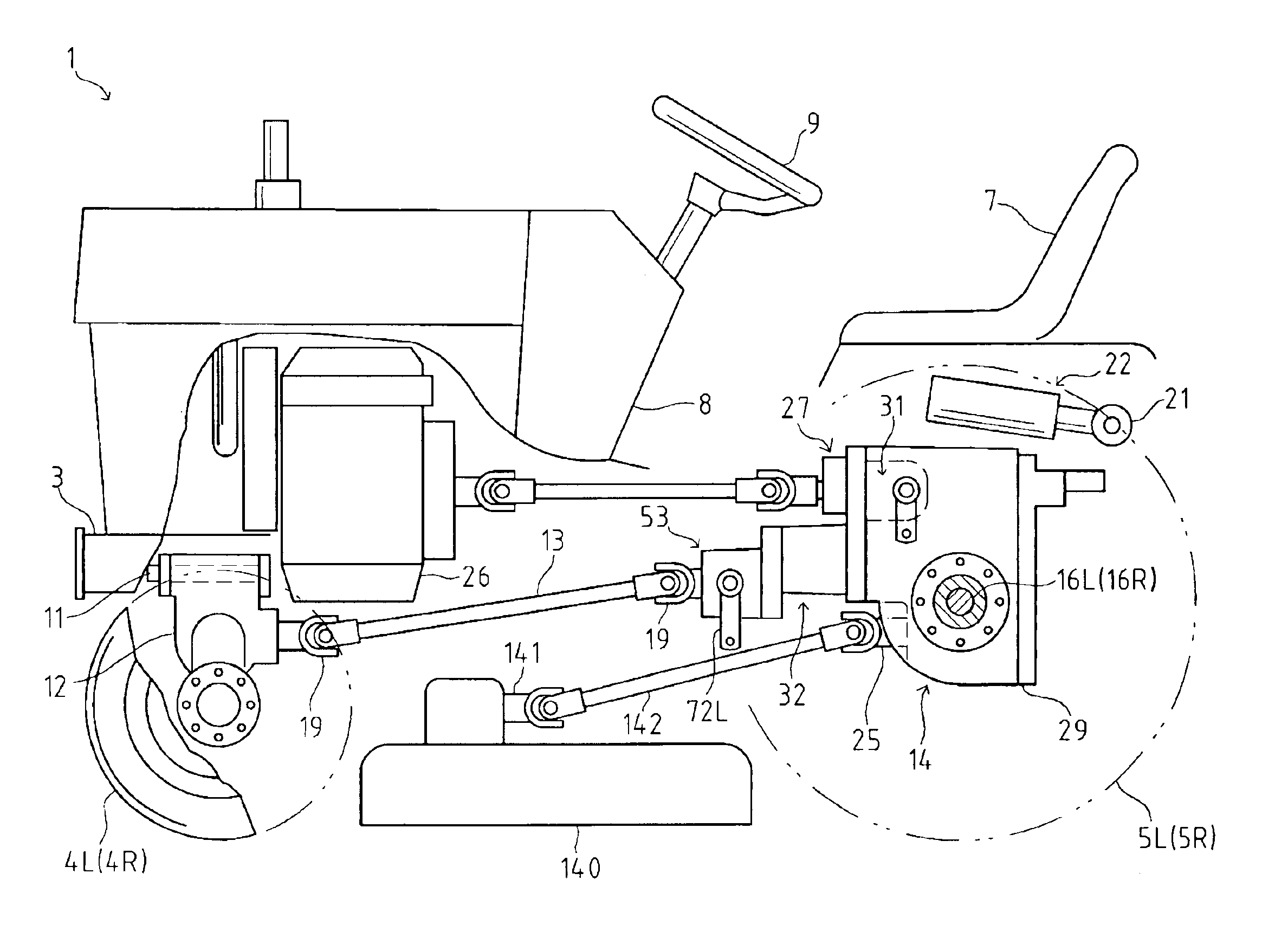
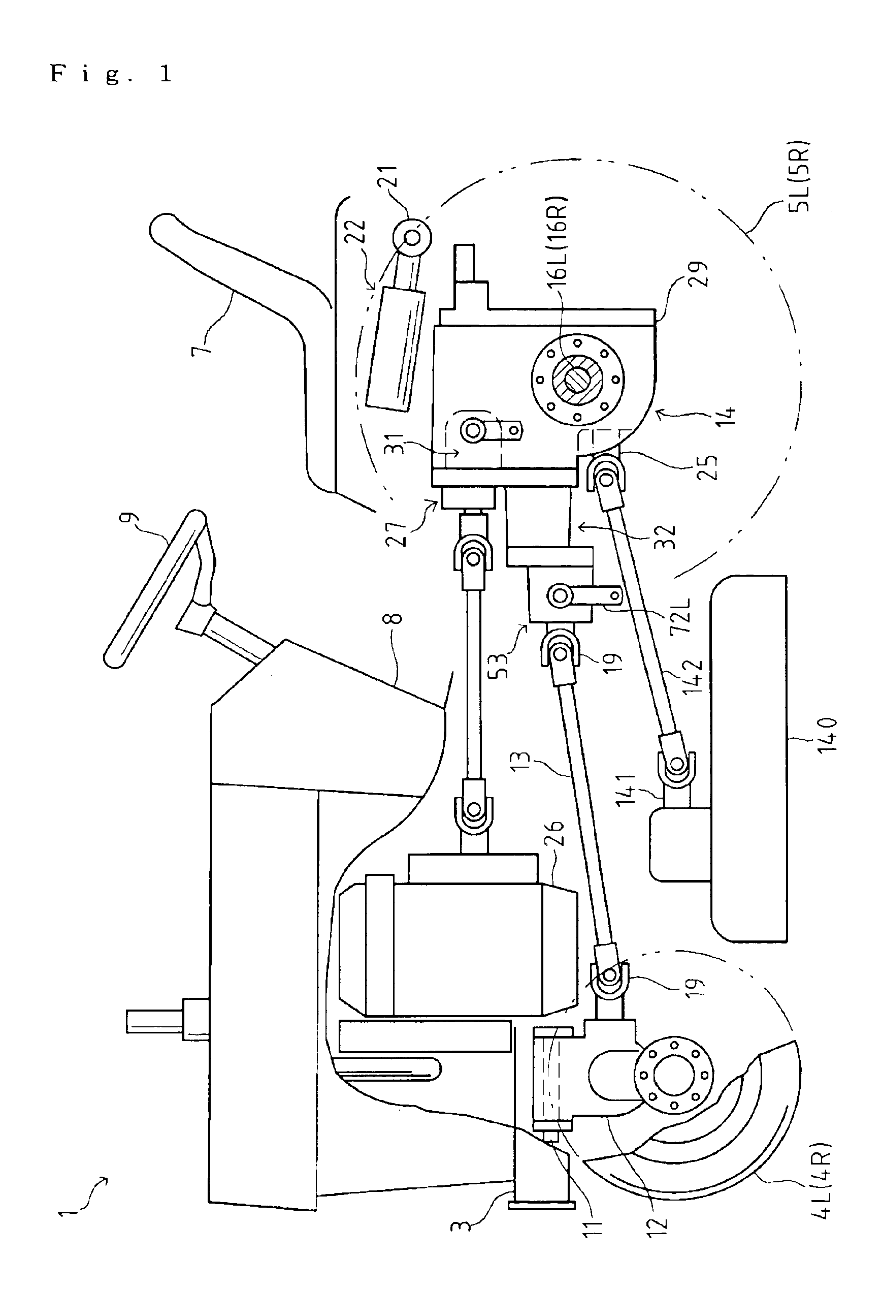
[0024]As shown in FIG. 1, a (mid-mount mower type) lawn tractor 1 serving as a four-wheel drive vehicle according to an embodiment of the present invention has a vehicle frame 3 extended in its longitudinal direction. Left and right rear ends of the vehicle frame 3 are attached to a front portion of a transmission casing 29 incorporating a transmission system 14. Left and right rear axle casings are laterally extended from left and right side surfaces of the transmission casing 29 supporting left and right rear axles 16L and 16R, respectively Unsteerable rear wheels 5L and 5R are attached onto outer ends of the rear axles 16L and 16R, respectively.

[0025]A mower 140 is supported at the intermediate bottom portion of the tractor 1. A mid PTO shaft 25 for driving the mower 140 projects forward from a lower portion of the transmission casing 29. An upper portion of the mower 140 supports a vertical input shaft 141. The input shaft 141 and the mid PTO shaft 25 are mutually connected thro...


PUM


Abstract

A hydraulic four-wheel driving apparatus is provided for a vehicle having a pair of left and right unsteerable wheels and a pair of left and right steerable wheels. The hydraulic four-wheel driving apparatus comprises: a transmission casing supporting the unsteerable wheels; a hydraulic pump disposed integrally with the transmission casing, the hydraulic pump being driven by a power source outside the transmission casing; a first hydraulic motor for driving the unsteerable wheels fluidly connected to the hydraulic pump, the first hydraulic motor being disposed integrally with the transmission casing; and a second hydraulic motor for driving the steerable wheels fluidly connected to the hydraulic pump, the second hydraulic motor being disposed integrally with the transmission casing and disposed on one side of the first hydraulic motor toward the steerable wheels.

Description

BACKGROUND OF THE INVENTION[0001]1. Field of the Invention[0002]The present invention relates to a hydraulic four-wheel driving apparatus for a vehicle.[0003]2. Related Art[0004]Conventionally, there is a well-known hydraulic four-wheel drive system for a vehicle (such as a lawn tractor) having a pair of left and right unsteerable (rear) wheels and a pair of left and right steerable (front) wheels, wherein the system includes a front-wheel speed-increasing mechanism for increasing drive speed of its front (steerable) wheels so as to prevent the front wheels from being dragged while the vehicle is turning because of uneven distance between the front wheels and the rear (unsteerable) wheels from the turning center of the vehicle when turning. With respect to the front-wheel speed-increasing mechanism disclosed in Japanese Patent No. 2,594,951, for example, one assembly unit of a hydraulic motor and a differential gearing is provided for driving the unsteerable rear wheels, and another...

Claims


Application Information

Patent Timeline
IPC IPC(8): B60K17/28B60K17/10B60K17/356B60K17/34B60K17/00B60K17/348
CPCB60K17/105B60K17/28B60K17/356B60Y2200/221
Inventor SAKIKAWA, SHIGENORIKAWAKAMI, MANABU
Owner KANZAKI KOKYUKOKI MFG
Why Eureka
Try Eureka