Heating control system for gas sensor of engine

a technology of heat control system and gas sensor, which is applied in the direction of electrical control, instruments, material electrochemical variables, etc., can solve the problem of relatively low heat exchange performance of gas sensors, and achieve the effects of preventing damage to gas sensors, reducing the delay in the starting time of activation energization control, and reducing the delay in the starting time of the activation energization control

Inactive Publication Date: 2005-08-30
DENSO CORP
View PDF11 Cites 15 Cited by
  • Summary
  • Abstract
  • Description
  • Claims
  • Application Information

AI Technical Summary

Benefits of technology

[0010]It is therefore an object of the present invention to provide a control system for a gas sensor of an internal combustion engine capable of preventing damage to the gas sensor.
[0012]While there is a possibility that the water droplets exist in the exhaust pipe, heating performance of the gas sensor is relatively low. In such a case, water droplets do not receive heat rapidly even if the water droplets adhere to the surface of the gas sensor. As a result, damage to the gas sensor can be prevented.
[0013]Furthermore, if there is no droplet in the exhaust pipe, the gas sensor is heated immediately. Therefore, delay in starting timing of the activation energization control can be minimized. Thus, requirement for quick increase in the gas sensor temperature can be met.
[0014]According to another aspect of the present invention, a heating control system, which controls energization to a heater of a gas sensor disposed in an exhaust pipe of an internal combustion engine, has preheat energization controlling means. The preheat energization controlling means performs preheat energization control before activation energization control for energizing the gas sensor with electric power capable of heating the gas sensor to the activation temperature. The preheat energization controlling means energizes the gas sensor with lower electric power in the preheat energization control than in the activation energization control so that water droplets in the gas sensor vaporize gradually. Thus, even if the water droplets exist in the gas sensor, the water droplets are vaporized gradually, preventing bumping of the water droplets. Therefore, the bumping of the water droplets is prevented when the activation energization control is performed. In addition, the temperature of the gas sensor has been heated to some extent by the time when the water droplets in the gas sensor vaporize sufficiently and the activation energization control is started. Therefore, the gas sensor can be heated to the activation temperature quickly. If the water droplets penetrate the diffusion layer and the like into the gas sensor from the outside during the engine is stopped and if the gas sensor is heated with the electric power capable of heating the gas sensor to the activation temperature, the heat of the gas sensor may produce bumping of the water, and the gas sensor may be damaged.

Problems solved by technology

While there is a possibility that the water droplets exist in the exhaust pipe, heating performance of the gas sensor is relatively low.

Method used


Image

  • Heating control system for gas sensor of engine
  • Heating control system for gas sensor of engine
  • Heating control system for gas sensor of engine

Examples


first embodiment

[0025](First Embodiment)

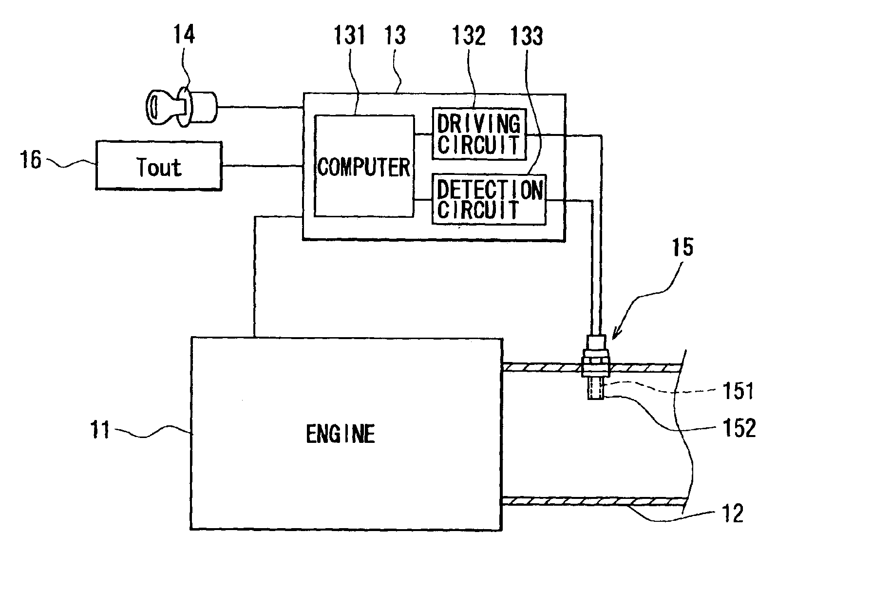
[0026]Referring to FIG. 1, an internal combustion engine having a heating control system of a gas sensor according to the first embodiment is illustrated. The first embodiment is applied to an automobile, for instance. An engine main body 11 of the internal combustion engine has a common structure. The engine main body 11 generates motive energy by combusting fuel and discharges exhaust gas to an exhaust pipe 12.

[0027]Various parts of the engine main body 11 are controlled by an electronic control unit (ECU) 13. The ECU 13 has a basic structure used in the common internal combustion engine. The ECU 13 starts the engine main body 11 if an ignition key 14 is switched on and controls torque or rotation speed based on information such as a throttle opening degree.

[0028]Various sensors provide information on operating conditions, which is used in the control performed by the ECU 13. As one of the sensors outputting detection signals to the ECU 13, an air fuel rati...

second embodiment

[0062](Second Embodiment)

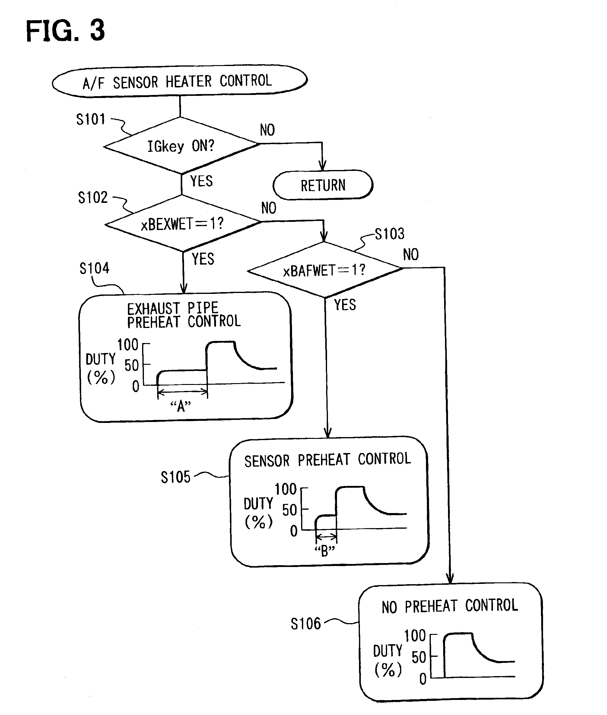
[0063]Next, control of the energization to the heater 22 of the A / F sensor 151 performed by an ECU 13 according to the second embodiment will be explained based on a flowchart shown in FIG. 6.

[0064]The control performed by the ECU 13 according to the second embodiment is generally similar to that of the first embodiment. However, in the energization control according to the second embodiment, the duty ratio of the driving current applied to the heater 22 of the A / F sensor 151 is set in a method different from that of the control according to the first embodiment. The processing flow for setting the duty ratio is shown in the flowchart in FIG. 6. The processing shown in FIG. 6 is started when the engine is started, or when the ignition key 14 is switched on.

[0065]In Step S401, the ambient temperature Tout is inputted. Then, in Step S402, it is determined whether the water is adhering to the exhaust pipe 12 based on the determination flag xBEXWET. If the resul...

third embodiment

[0074](Third Embodiment)

[0075]Next, energization control of the heater 22 of the gas sensor 151 performed by an ECU 13 according to the third embodiment will be explained based on a flowchart shown in FIG. 8.

[0076]The control performed by the ECU 13 according to the third embodiment is generally similar to that of the first embodiment. However, in the energization control performed by the ECU 13 of the third embodiment, a duty ratio of the driving current applied to the heater 22 of the A / F sensor 151 is set in a method different from that of the first embodiment.

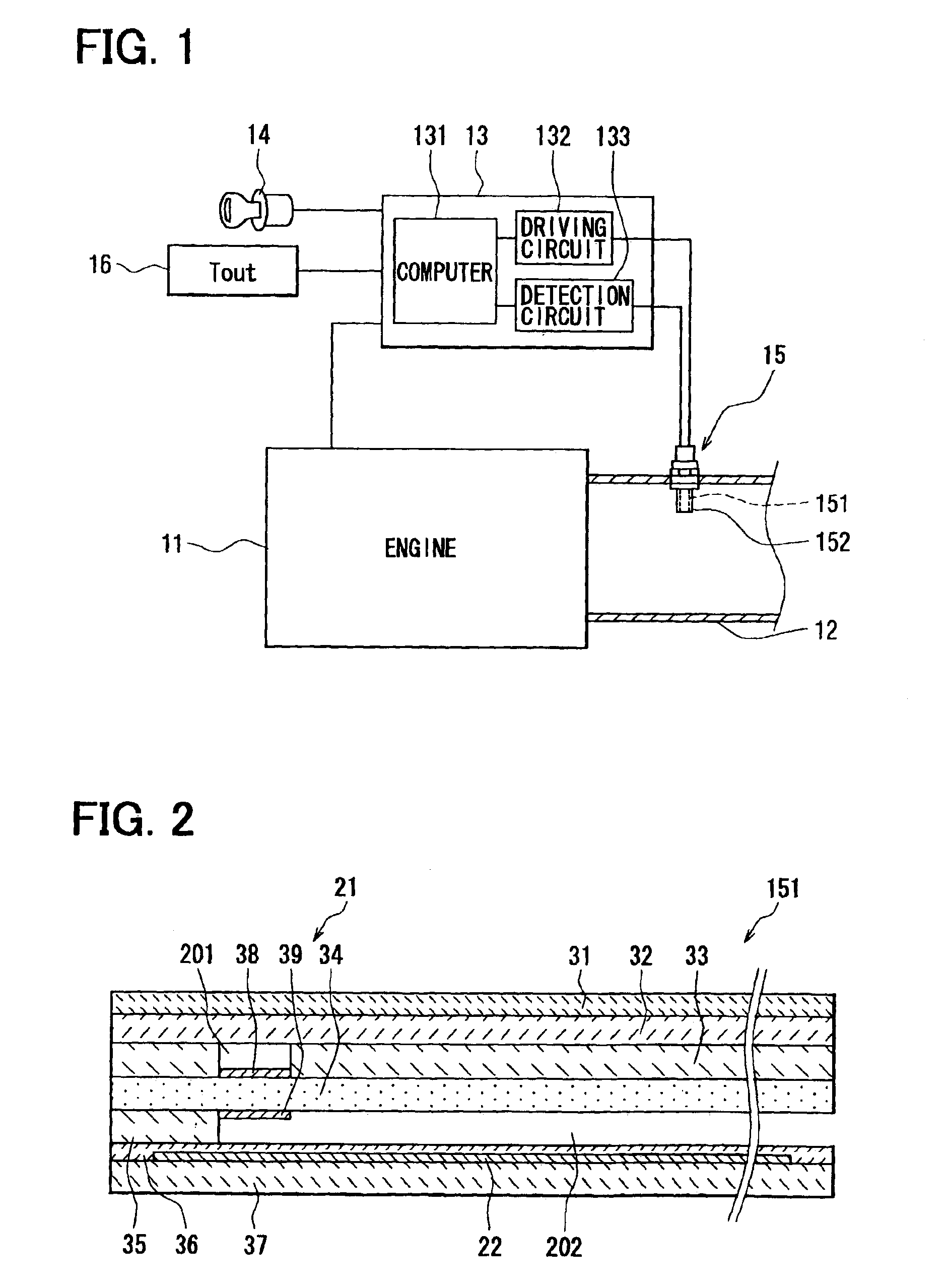
[0077]First, in Step S501, resistance RI between the electrodes 38, 39 of the pump cell 21 of the A / F sensor 151, or element resistance RI, is detected. The element resistance RI correlates with temperature Te of the A / F sensor 151 as shown in FIG. 9. Therefore, the element resistance RI is employed as a parameter of the temperature Te of the A / F sensor 151. More specifically, a general method to calculate the element resis...


PUM

PropertyMeasurementUnit
boiling pointaaaaaaaaaa
temperatureaaaaaaaaaa

Abstract

An electronic control unit of an internal combustion engine performs preheat energization control before activation energization control. In the activation energization control, a gas sensor is energized with electric power capable of heating the gas sensor to activation temperature. In the preheat energization control, the gas sensor is energized with low electric power, which is not enough to heat the gas sensor to the activation temperature. Thus, while there is a possibility that water adheres to a sensor main body of the gas sensor, the sensor main body is prevented from being heated to high temperature. Meanwhile, even if water droplets exist in the sensor main body of the gas sensor, the water is vaporized gradually, while preventing the bumping of the water.

Description

CROSS REFERENCE TO RELATED APPLICATION[0001]This application is based on and incorporates herein by reference Japanese Patent Application No. 2002-232851 filed on Aug. 9, 2002.BACKGROUND OF THE INVENTION[0002]1. Field of the Invention[0003]The present invention relates to a heating control system for a gas sensor of an internal combustion engine, in particular, to a method of preventing damage to the gas sensor.[0004]2. Description of Related Art[0005]An internal combustion engine has a gas sensor in an exhaust pipe for detecting concentration of gas such as oxygen included in exhaust gas discharged from an engine main body. Detection signals provided by the gas sensor are used in control of various parts of the engine main body.[0006]A publicly used gas sensor is constituted with a base substrate made of an oxygen-ion conductive solid electrolyte such as zirconia. Such a gas sensor utilizes an attribute of the oxygen-ion to diffuse into the solid electrolyte. In the gas sensor, a c...

Claims


Application Information

Patent Timeline
Patent Type & Authority Patents(United States)
IPC IPC(8): G01N27/406G01N27/41
CPCG01N27/4067
Inventor MORINAGA, SYUJIROSHIMIZU, KOUICHI
Owner DENSO CORP
Why Eureka
Try Eureka