Projector

a projector and projector technology, applied in the field of projectors, can solve the problems of difficult installation of cooling fans, optical characteristics may drop, distortion and deterioration of polarizing plates, etc., and achieve the effects of reducing temperature rise, high thermal conductivity, and relatively high thermal conductivity of the base fram

Inactive Publication Date: 2005-08-30
SEIKO EPSON CORP
View PDF106 Cites 33 Cited by
  • Summary
  • Abstract
  • Description
  • Claims
  • Application Information

AI Technical Summary

Benefits of technology

[0011]In the above apparatus, it is preferable that the base frame is made of metal. By so doing, the thermal conductivity of the base frame can be made relatively high, and so it becomes possible to reduce the temperature rise due to the heat generation of polarization control element.
[0012]In the above apparatus, the polarization control component may be held by a metal holder that makes contact with the light-transmissive member, and the light-transmissive member and the base frame may be thermally coupled via at least the holder. Even if a metal holder of relatively high thermal conductivity is interposed between the light-transmissive member and the base frame, heat generated by the polarization control element can be transferred to the base frame, and temperature rise due to heat generation of the polarization control element can be reduced. Also, a plurality of members of relatively high thermal conductivity can be interposed between the base frame and the light-transmissive member which is stuck to the polarization control element.
[0013]Here, the holder may be fixed to the base frame via an adhesive sheet or adhesive, or by metal welding. Also the light-transmissive member may be fixed to the holder via an adhesive sheet or adhesive. It is preferable that the adhesive sheet or adhesive has relatively high thermal conductivity. In this way, in the case that an adhesive or adhesive sheet of relatively small thickness is interposed between the holder and the base frame, the holder and the base frame are not contacting directly, but are close, so that heat generated by the polarization control element can be transmitted to the base frame. The case where an adhesive sheet or adhesive is interposed between the light-transmissive member and the holder is similar. If the holder and base frame are joined by metal welding, heat generated by the polarization control element can be transferred efficiently to the base frame.
[0014]That is, the aforementioned “thermally coupled” state will be a state relatively easy heat transfer, and includes a state in which an adhesive or adhesive sheet of relatively small thickness is interposed between the light-transmissive member and base frame.
[0015]In the above apparatus, the holder may include: a fixing section fixed to the base frame; and an attaching section for attaching the light-transmissive member to the fixing section. Here, the fixing section may be fixed to the base frame via an adhesive sheet or adhesive, or by metal welding. Also, the light-transmissive member may be stuck to the fixing section and / or the attaching section via an adhesive sheet or adhesive.
[0016]It is preferable that the above apparatus further includes a metal chassis for housing all optical components arranged on the optical path from the illumination optical system to the projection optical system. In this case, it is preferable that the base frame and the chassis are thermally coupled. This arrangement allows heat generated by the polarization control element to be transferred from the base frame to the chassis, so temperature rise due to heat generation of polarization control element can be reduced.

Problems solved by technology

If due to this heat generation the temperature of the polarizing plate rises, distortion and deterioration of the polarizing plate may occur, and optical characteristics may drop.
However, when miniaturizing a projector, it may be difficult to install a cooling fan, or it will be necessary to miniaturize the cooling fan.
In such cases, there has been the problem that the polarizing plate cannot be cooled adequately, and the temperature rise of the polarizing plate becomes relatively large.
This problem is common to any optical elements including organic material for controlling the polarization state of light exiting from the optical elements (hereinafter also termed “polarization control elements”).

Method used


Image

  • Projector
  • Projector
  • Projector

Examples


first embodiment

A.

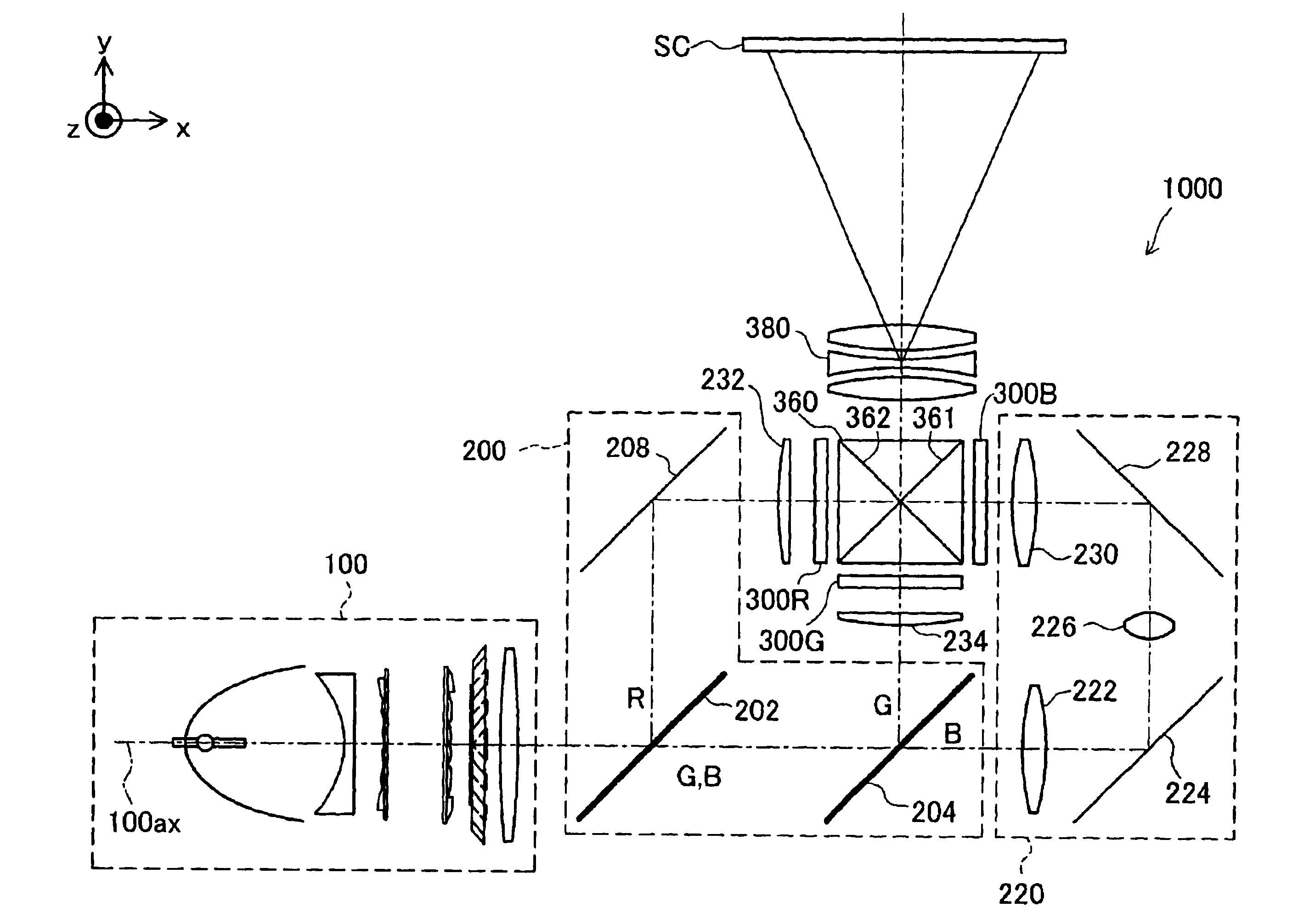
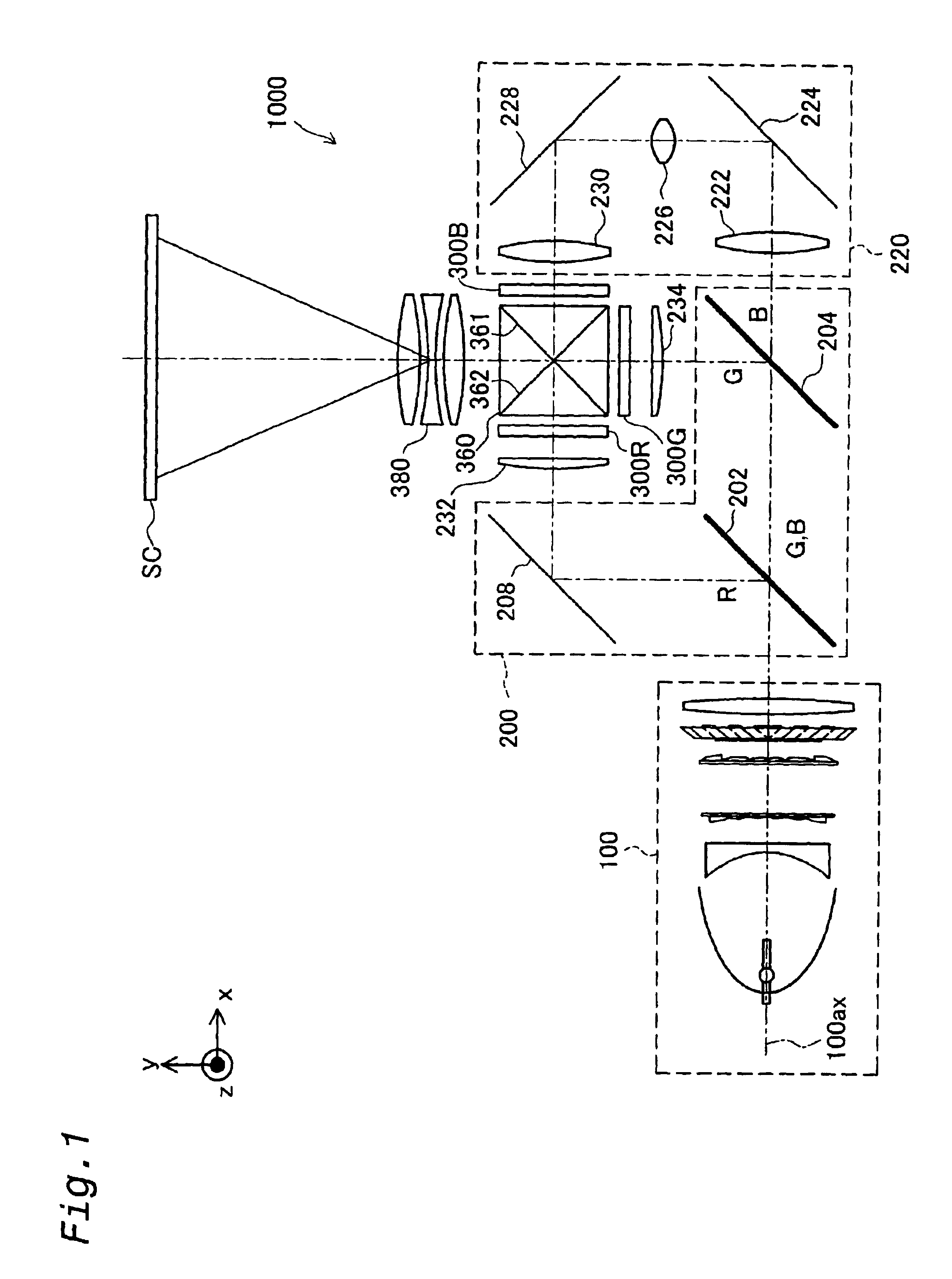
[0053]One mode of carrying out the present invention is discussed below as a preferred embodiment. FIG. 1 is a simplified schematic diagram showing an example of a projector. Projector 1000 comprises an illumination optical system 100, a color separation optical system 200, a relay optical system 220, three liquid crystal light valves 300R, 300G, 300B, a cross dichroic prism 360, and a projection optical system 380.

[0054]Light output from the illumination optical system 100 is separated by the color separation optical system 200 into colored light of the three colors of red (R), green (G) and blue (B). The separated colored lights are modulated by liquid crystal light valves 300R, 300G, 300B in response to image information. Modulated lights are combined by the cross dichroic prism 360, and the composite light is projected onto a screen SC by the projection optical system 380. By means of this an image is displayed on the screen SC.

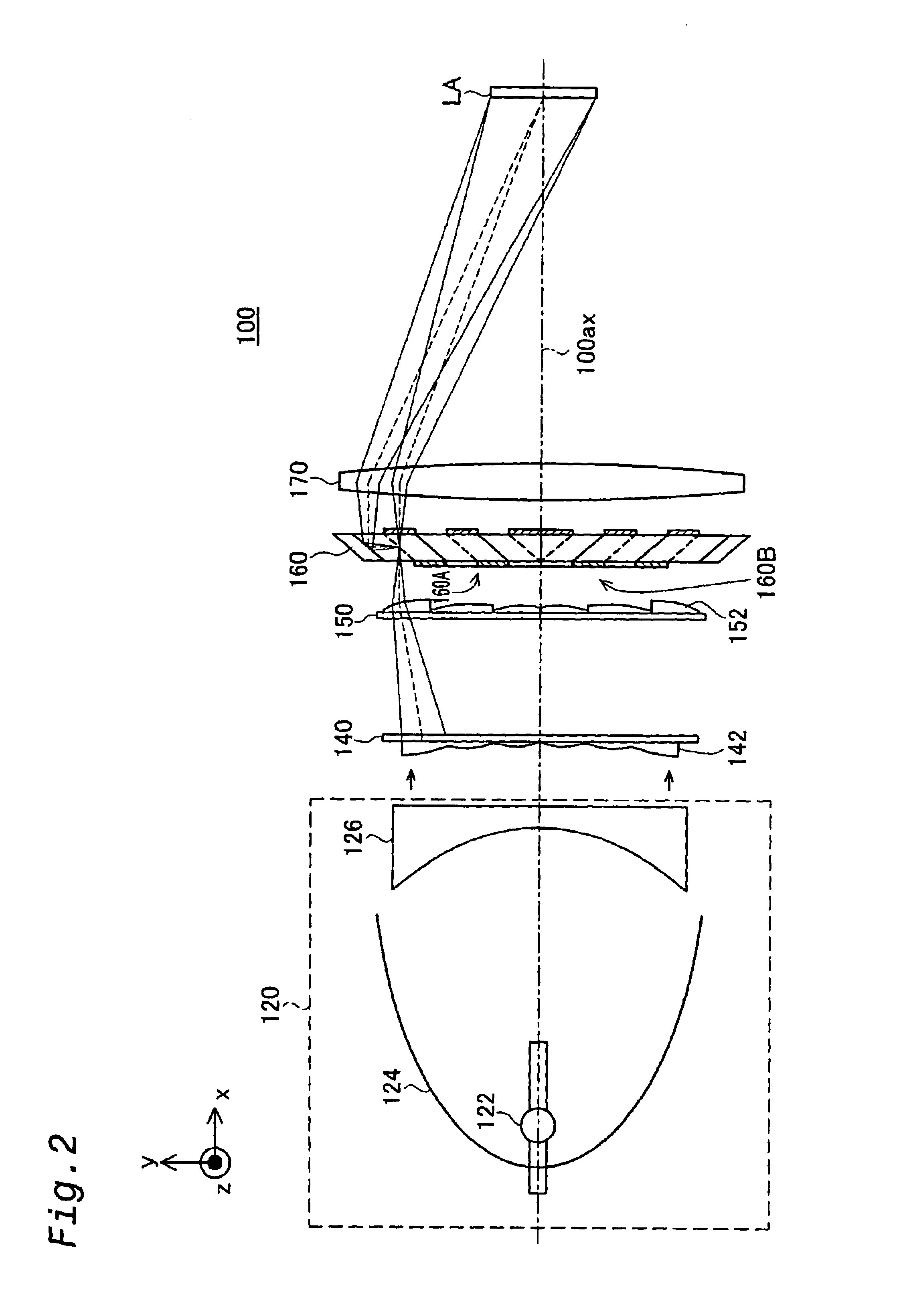
[0055]FIG. 2 is an illustrative diagram showing a...

second embodiment

B.

[0117]In the First Embodiment, as shown in FIGS. 6 and 8, the first polarizing plate 320Gi, together with the light-transmissive substrate 321, constitutes a polarization control component, but instead of this, the plate 320Gi, together with the field lens 234, may constitute a polarization control component.

[0118]FIG. 10 is an explanatory diagram showing a field lens 234′ with the first polarizing plate 320Gi stuck to it. This field lens 234′ is formed of sapphire. As shown in the drawing, the first polarizing plate 320Gi is stuck to the flat face of the plano-convex field lens 234′.

[0119]FIG. 11 is an explanatory diagram showing a holder 750 that holds a polarization control component consisting of the first polarizing plate 320Gi and the field lens 234′ shown in FIG. 10. The holder 750 comprises a metal fixing section 752 and an attaching section 754. The fixing section 752 has a cross sectional shape of a roughly L-shape, and a roughly circular opening on the face through whic...

third embodiment

C.

[0130]In the First Embodiment, as shown in FIGS. 6 and 9, the third polarization control component consisting of the liquid crystal panel 310G and the pair of light-transmissive substrates 311, 312 is held by the holder 730, and the holder 730 is directly fixed to the base frame 600, but the holder could also be fixed to the base frame 600 via some other part.

[0131]FIG. 14 is an explanatory diagram showing a holder 730A that holds the third polarization control component consisting of the liquid crystal panel 310G and the pair of light-transmissive substrates 311, 312. The holder 730A is substantially similar to the holder 730 of FIG. 9, but a fixing section 732A is modified. Specifically, the fixing section 732A of this embodiment has two projecting portions.

[0132]As explained in FIG. 9, the fixing section 732A and attaching section 734 are joined together with the third polarization control components 310G, 311, 312 sandwiched between. Also, in this embodiment the holder 730A is...


PUM


Abstract

This invention provides a technique of reducing temperature rise due to heat generation of polarization control elements. A projector includes: an illumination optical system; an electro-optical device for modulating light from the illumination optical system in response to image information; a projection optical system for projecting modulated light obtained with the electro-optical device and a base frame, formed using material including metal material, for mounting a plurality of optical components arranged on an optical path from the illumination optical system to the projection optical system. At least one of the plurality of optical components is a polarization control component that includes: a polarization control element including organic material for the controlling polarization state of light exiting from the polarization control element; and a light-transmissive member having a thermal conductivity of at least about 0.8 W/(m·K), to which the polarization control element is stuck. The light-transmissive member and the base frame are thermally coupled.

Description

TECHNICAL FIELD[0001]This invention relates to a projector for projecting and displaying images.BACKGROUND ART[0002]Projectors display images by modulating light from an illumination optical system in response to image information (image signal) by means of a liquid crystal panel, and projecting the modulated light onto a screen.[0003]A liquid crystal light valve is typically composed of a liquid crystal panel, and a polarizing plate provided to the light incident side and / or light exiting side thereof The polarizing plate allows transmission of only the component of light in the direction of the polarization axis, and blocks other components of light. Where a polarizing plate includes organic material, the polarizing plate absorbs light other than the light component in the direction of the polarization axis, and thus generates heat. If due to this heat generation the temperature of the polarizing plate rises, distortion and deterioration of the polarizing plate may occur, and opti...

Claims


Application Information

Patent Timeline
Patent Type & Authority Patents(United States)
IPC IPC(8): G02B27/28G02B7/00H04N9/31G03B21/14G03B21/16G03B21/20
CPCG02B7/008G02B27/283G03B21/16H04N9/3105H04N9/3144H04N9/3197G03B21/145G03B21/2073
Inventor TAKEZAWA, TAKESHIHASHIZUME, TOSHIAKIFUJIMORI, MOTOYUKIYANAGISAWA, YOSHIYUKI
Owner SEIKO EPSON CORP
Why Eureka
Try Eureka