Echogenic needle for transvaginal ultrasound directed reduction of uterine fibroids and an associated method

a technology of uterine fibroids and ultrasound, which is applied in the direction of ultrasonic/sonic/infrasonic diagnostics, applications, tomography, etc., can solve the problems of affecting the patient's recovery, and carries the usual risk of surgery, so as to achieve heightened visibility and facilitate the manipulation of the needle. , the effect of enhancing the visibility

Inactive Publication Date: 2005-08-30
GYNESONICS
View PDF20 Cites 136 Cited by
  • Summary
  • Abstract
  • Description
  • Claims
  • Application Information

AI Technical Summary

Benefits of technology

[0015]In a third embodiment, the needle has an outer member, an inner surface, an echogenic distal end, and a proximal end. As in the first embodiment, the echogenic material results in the tip of the needle having a heightened visibility. Within the outer member is a cryogen tube that extends longitudinally from the proximal end to the distal end. Surrounding a section of the outer member from the proximal end to near the distal end is a cryo-insulation sheath. The distal end is in communication with a cryogen supply so that the distal end can be in cryogenic contact with fibroids.
[0016]The length of the needle in all embodiments is typically from about 25 to 50 centimeters, and somewhat more typically between 30 to 40 centimeters. The diameter of the needle in all embodiments is typically from about 12 to 18 gauge, and somewhat more typically from about 16 to 18 gauge. Normally, the needle has a handle at the proximal end that allows the user to easily grip and manipulate the needle.

Problems solved by technology

Hysterectomy is a major surgical procedure and carries with it the usual risk of surgery, such as hemorrhaging, lesions, complications, pain, and prolonged recovery.
Abdominal myomectomy and laparoscopic myomectomy, like a hysterectomy, carries the usual risk of surgery.
Direct visualization is often problematic because of the difficulties involved in simultaneously manipulating the endoscope and needle.
Similar to an endoscope, a hysteroscope must be simultaneously manipulated with the needle, and thus is problematic.
For example, a clinician using ultrasound imaging from an external source will have difficulty in distinguishing the uterine tissue from the surrounding organs and precisely locating the needle.
As a result, uterine adhesions often form that may cause chronic pain, infertility, and bowel obstruction.
Additionally, during laparoscopic surgery the surgeon cannot visualize the tissue below the surface and must blindly place the needle, as a result placement may be sub-optimal.
There is the risk that the needle guide could shift during removal of the endoscope and insertion of the ablation device, resulting in sub-optimal performance.
Reinserting and removing the endoscope and ablation device every time the needle must be repositioned increases the time and expense of the surgery.
The cryo / electro needle is not easily visualized when in use and requires the use of a dilator to create an access channel in the tissue area where the needle is to be inserted.
Similar to laparscopic surgery, placement of the cryo / electro needle is done blindly and may not result in optimal performance.

Method used


Image

  • Echogenic needle for transvaginal ultrasound directed reduction of uterine fibroids and an associated method
  • Echogenic needle for transvaginal ultrasound directed reduction of uterine fibroids and an associated method
  • Echogenic needle for transvaginal ultrasound directed reduction of uterine fibroids and an associated method

Examples


first embodiment

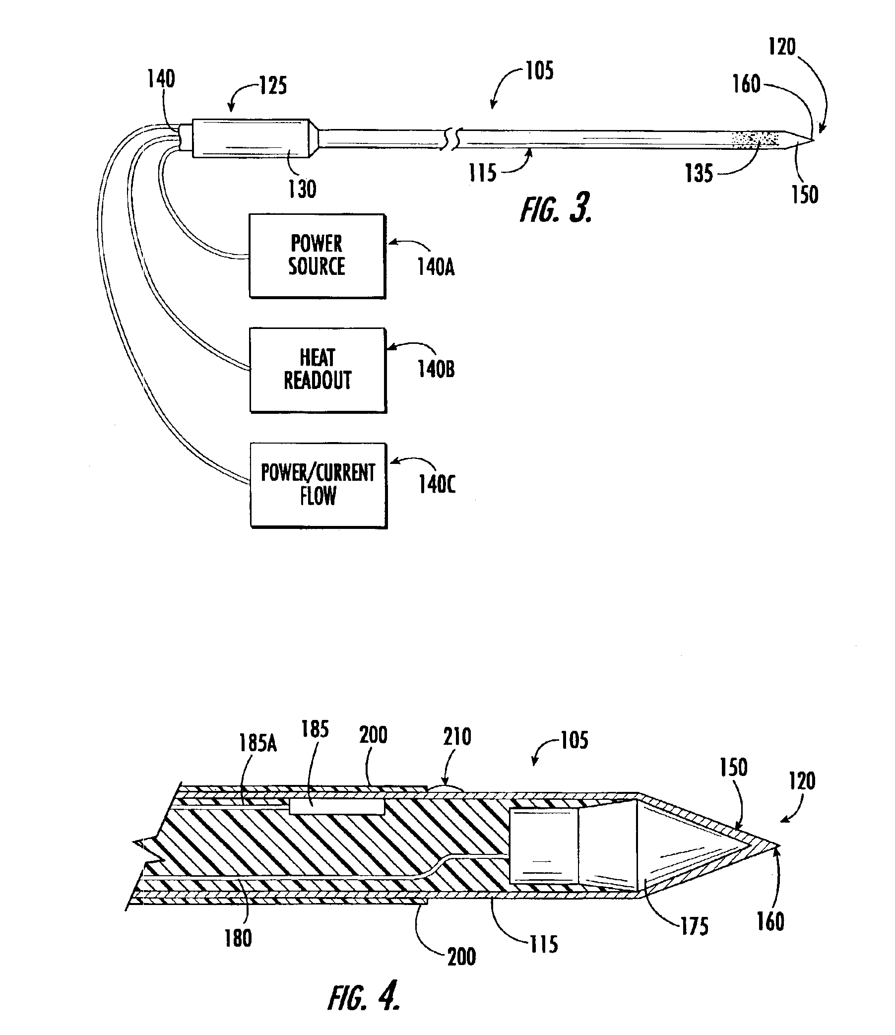
[0039]In FIG. 4, the active electrode 175 is depicted at the distal end 120 within the needle. In this first embodiment, the distal end's noninsulated outer surface 150 is electrically conductive so that RF energy passes from the active electrode 175 into fibroid tissue. The distal end 120 has a sharpened tip 160 that can penetrate fibroid tissue to deliver RF energy within the fibroid. As shown in FIG. 4, the RF needle optionally has a temperature sensor 185 disposed near the distal end 120. Typically, the temperature sensor will be disposed near the tip of the needle or within the insulation sheath. Normally, the temperature sensor is a thermocouple or thermistor. The sensor provides information that enables the physician to monitor tissue temperature and to adjust the power accordingly.

[0040]With reference to FIGS. 5 through 9, reference number 400 broadly designates a RF needle having a RF energy “shut-off” mechanism. The shut-off mechanism turns off RF energy to the active elec...

second embodiment

[0045]In a needle having a safety mechanism 400, the active electrode is located at the blunt rear end. As shown in FIG. 8, the active electrode 175 is located at the blunt rear end 425 and an electrical connector 425a extends longitudinally from the conductive surface 410 to the active electrode 175. The outer member 115 has a second conductive surface 420 that is in communication with RF power supply, but rather than having a third surface in communication with the active electrode, the conductive surface 410 on the inner member 405 is in communication with the active electrode 175. When pressure is applied to the blunt rear end 425, the spring 430 compresses and the inner member retracts into the outer member. As a result, the conductive surfaces 410, 415 contact one another and RF current is applied to the active electrode 175. Typically, the electrical connector 425a is disposed within the inner member 405.

[0046]However, the electrical connector 425a may be disposed between the...

third embodiment

[0047]In a RF needle with a safety mechanism 400, the inner member is connected to a switch. With reference to FIG. 9, a needle is shown having an inner member 405 attached to a switch 450. The switch 450 is in communication with a RF power source via line 455. As pressure is applied to the blunt rear end 425 the inner member 405 retracts into the outer member 115 and closes the switch 450. When in the closed position, the switch 450 sends an electrical signal through line 455 to the RF power supply 140a and RF energy is delivered to the active electrode. The active electrode is located at the distal end and is in communication with the switch, or alternatively, the noninsulated distal end 120a is the active electrode.

[0048]In all the embodiments of a needle having a safety mechanism 400 the inner member 405 is typically made from a material that is non-conductive, such as a plastic. Normally, a non-conductive member will have a conductive material, such as stainless steel, inserted...


PUM


Abstract

The invention is a transvaginal ultrasound probe having an attached echogenic needle that is useful in the treatment of uterine fibroids. The echogenic needle has an echogenic surface near its tip that allows the physician to visualize its location using ultrasound imaging. In one embodiment, the needle has an active electrode at its distal end. The active electrode supplies radio frequency energy to a fibroids causing necrosis of the targeted fibroid or by destroying the fibroid's vascular supply. The radio frequency needle preferably has a safety device that shuts-off energy if the needle punctures the uterine wall. In a second embodiment, the needle has a cryogen supply tube and cryogen supply. This embodiment destroys fibroid tissue by freezing it or its vascular supply when the tissue comes in contact with the needle's frozen distal end. The invention further includes the method of using the ultrasound probe with the attached needle.

Description

BACKGROUND OF THE INVENTION[0001]This invention relates to surgical needles for tissue ablation, and more particularly, to surgical needles that are for ablation of uterine fibroids.[0002]Approximately 20 to 40 percent of women have uterine fibroids (licomyomata). In the United States, fibroids result in approximately 175,000 hysterectomies and 20,000 myomectomies each year. Fibroids are well-defined, non-cancerous tumors that arise from the smooth muscle layer of the uterus. Approximately 25% of women suffer fibroid related symptoms, including menorrhagia (prolonged or heavy menstrual bleeding), pelvic pressure or pain, and reproductive dysfunction.[0003]The most common treatments for fibroids include hysterectomy, abdominal myomectomy, laparoscopic myomectomy, hysteroscopic myomectomy, laparoscopy-directed needle mylosis, laparoscopy-directed needle cryomyolysis, high-intensity focused ultrasound ablation of fibroids, and uterine artery embolization. Hysterectomy is a major surgic...

Claims


Application Information

Patent Timeline
Patent Type & Authority Patents(United States)
IPC IPC(8): A61B18/14A61B17/42A61B18/02A61B19/00A61B18/00A61B17/00
CPCA61B18/1477A61B17/42A61B18/02A61B19/201A61B2017/00084A61B2018/00559A61B2018/00791A61B2019/5276A61B2019/5278A61B2019/5425A61B90/11A61B2090/378A61B2090/3782A61B2090/3925
Inventor HURST, BRADLEY SHAWN
Owner GYNESONICS
Why Eureka
Try Eureka