Feed-dispersion system for fluid catalytic cracking units

a technology of fluid catalytic cracking and dispersion system, which is applied in the direction of furnaces, lighting and heating apparatus, furnace types, etc., can solve the problems of thermal cracking of still liquid fractions, formation of by-products such as coke and fuel gas, and unfavorable catalytic cracking on the riser bottom, so as to improve the conversion rate of feed, reduce the pumping power of hydrocarbon feed flow, and improve the effect of feed conversion

Inactive Publication Date: 2005-08-30
PETROLEO BRASILEIRO SA (PETROBRAS)
View PDF13 Cites 42 Cited by
  • Summary
  • Abstract
  • Description
  • Claims
  • Application Information

AI Technical Summary

Benefits of technology

[0032]The present invention provides still an atomization unit having an arrangement of the outlet nozzles that makes possible to operate with a ratio of the atomization fluid nozzles to feed equal or higher than 1.
[0033]The present invention provides further a feed-dispersion system that makes possible a better conversion of the feed into valuable products such as gasoline and naphtha.
[0034]The

Problems solved by technology

If a quick vaporization does not occur, the result is a thermal cracking of the still liquid fractions.
It is well known that the thermal cracking leads to the formation of by-products such as coke and fuel gas, mainly in the case of residuum-containing charges.
Therefore, the cracking on the riser bottom undesirably competes with the catalytic cracking that is the object of the FCC process.
However the feed temperature cannot be indefinitely increased since there is the risk of coke build up an

Method used


Image

  • Feed-dispersion system for fluid catalytic cracking units
  • Feed-dispersion system for fluid catalytic cracking units
  • Feed-dispersion system for fluid catalytic cracking units

Examples


example

[0080]TABLE 1 below presents the comparison between the performance of two feed-dispersion systems: a conventional one, adopted as the state-of-the-art control and another one a prototype of the present invention, the object of the present application. The tests were run in a FCC unit of a large Brazilian refinery, the feed features and operation conditions being kept constant. The results evidence a sensible increase in conversion to valuable fractions, particularly the cracked naphtha, with an increase of 3.08%. Further, there is a reduction in coke generation (9.46%) and fuel gas (15.65%), which agree with the mass and conversion balance. The numbers evidence the unequivocal dependence between the quality of charge injection obtained from the device of the invention and the yields of the catalytic cracking unit (FCC).

[0081]

TABLE 1Feed andTest 1Test 2conversion features(control)InventionDifferenceFeed (m3 / d)91179115−2D20 / 40.94180.9403RCR (% w)1.791.26RTX (° C.)540541+1CFT (° C.)27...


PUM

PropertyMeasurementUnit
Percent by massaaaaaaaaaa

Abstract

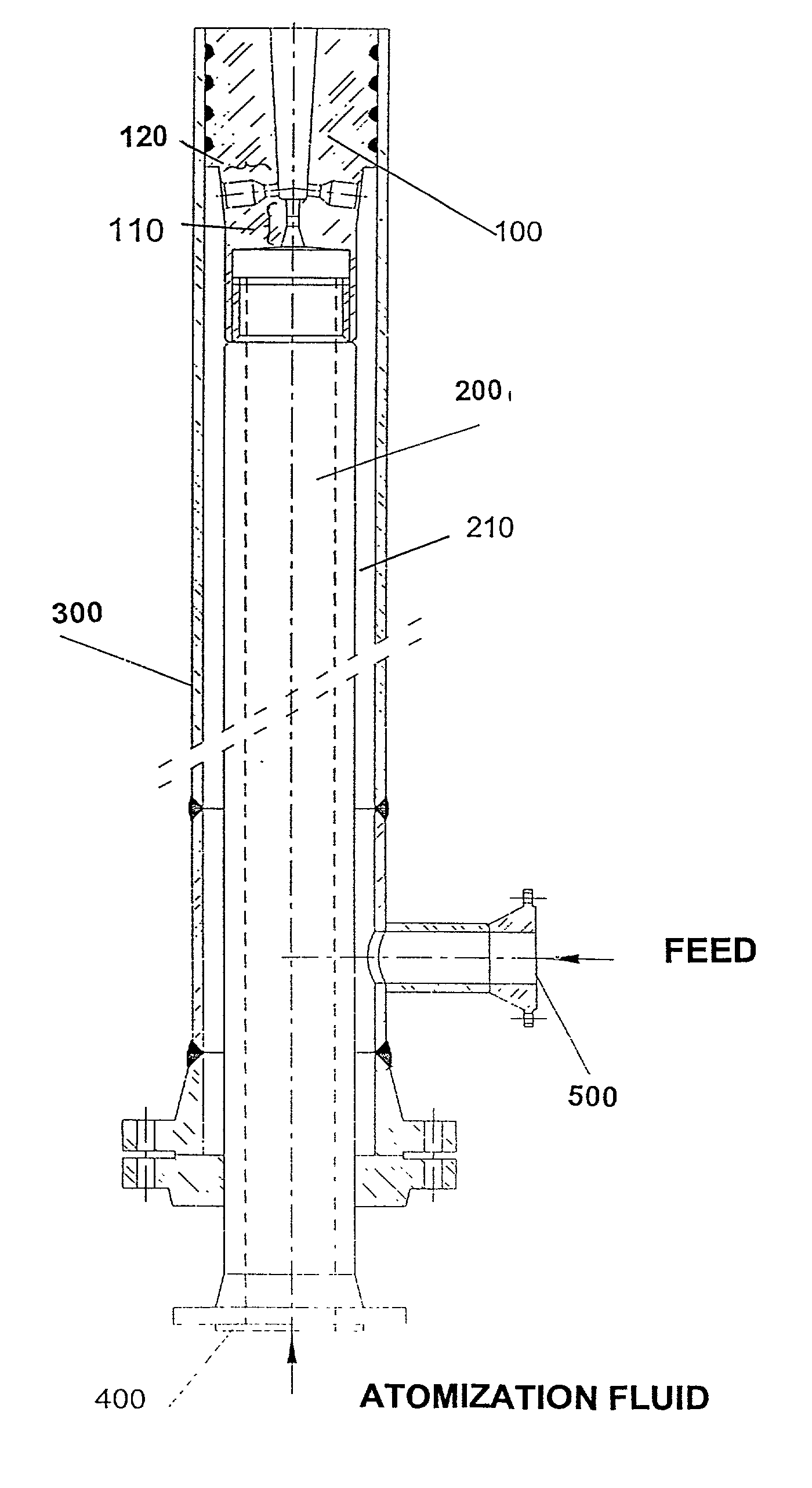
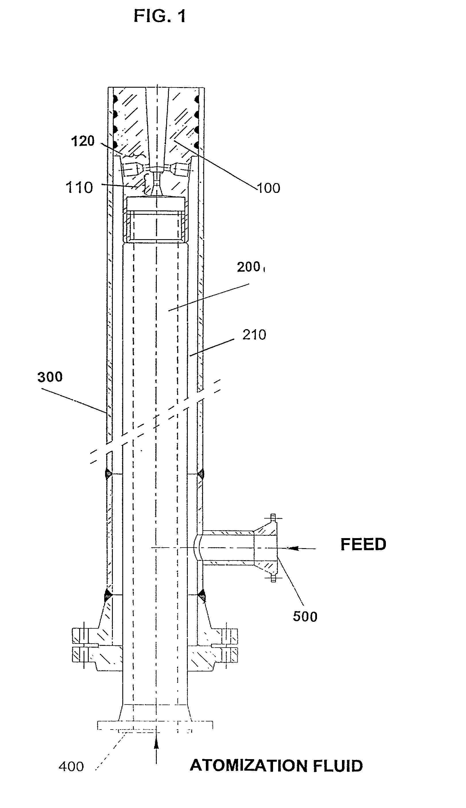
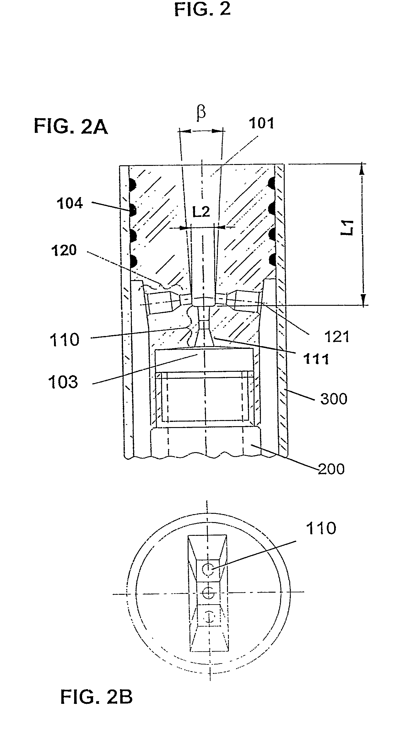
A feed-dispersion system for hydrocarbon feeds of fluid catalytic cracking units is described, which comprises:
    • a feed-injection system made up of two concentric conduits, where the atomization fluid flows through the inner conduit, while the liquid feed flows through the annular space formed by the outer surface of the inner conduit and the inner surface of the outer conduit;
    • an atomization unit having nozzles arranged in rows, with one row having central nozzles connected to the inner conduit for atomization fluid, and two or more rows of side nozzles, connected to the outer feed conduit, the central nozzles and side nozzles of the atomization unit being geometrically placed so that the energy of the atomization fluid is fully transferred by contact to the flow of feed, this resulting in the complete atomization of the feed;
    • a mixing chamber formed by the edges of the central nozzles, the dimensions of which are able to prevent the coalescence of the formed oil droplets.

Description

FIELD OF THE INVENTION[0001]The present invention relates to a feed-dispersion system for the optimized dispersion of hydrocarbon stocks as feeds for catalytic cracking units (FCC), more specifically, to a feed-dispersion system able to promote the full atomization of a hydrocarbon feed added or not of high boiling point fractions, said system comprising a unique geometrical arrangement so that the energy transferred from the atomizing fluid to the hydrocarbon feed is fully used for the feed atomization. The invention relates further to the FCC process that uses the feed-dispersion system of the invention.BACKGROUND INFORMATION[0002]Fluid catalytic cracking (FCC) is a main process for obtaining highly ranked petroleum related products, such as gasoline, diesel oil and liquid petroleum gas (LPG), from heavy feeds having usable light fractions. The feeds most often submitted to the FCC process are generally those refinery streams that have origin in side cuts of vacuum towers, called ...

Claims


Application Information

Patent Timeline
IPC IPC(8): C10G11/18C10G11/00B01F23/20B05B7/04
CPCC10G11/18
Inventor DE SOUZA, EDSON JOSE JOAQUIMDUBOIS, AURELIO MEDINABAPTISTA, CLAUDIO DAMIANCERAMOS, JOSE GERALDO FURTADODE FARIA, JOSE LORETO MOREIRABAMPI, MOACIR JOSE
Owner PETROLEO BRASILEIRO SA (PETROBRAS)
Why Eureka
Try Eureka