
Fluoropolymer reactor with heat exchange jacket

a fluoropolymer and heat exchange jacket technology, applied in the direction of fluid pressure control, halogenated hydrocarbon preparation, instruments, etc., can solve the problems of compromising the structural integrity of the reactor, corroding acutely, and strong acids forming which tend to corrode the reactor vessel

Inactive Publication Date: 2005-09-06
ALLIEDSIGNAL INC
View PDF21 Cites 20 Cited by
  • Summary
  • Abstract
  • Description
  • Claims
  • Application Information

AI Technical Summary

Benefits of technology

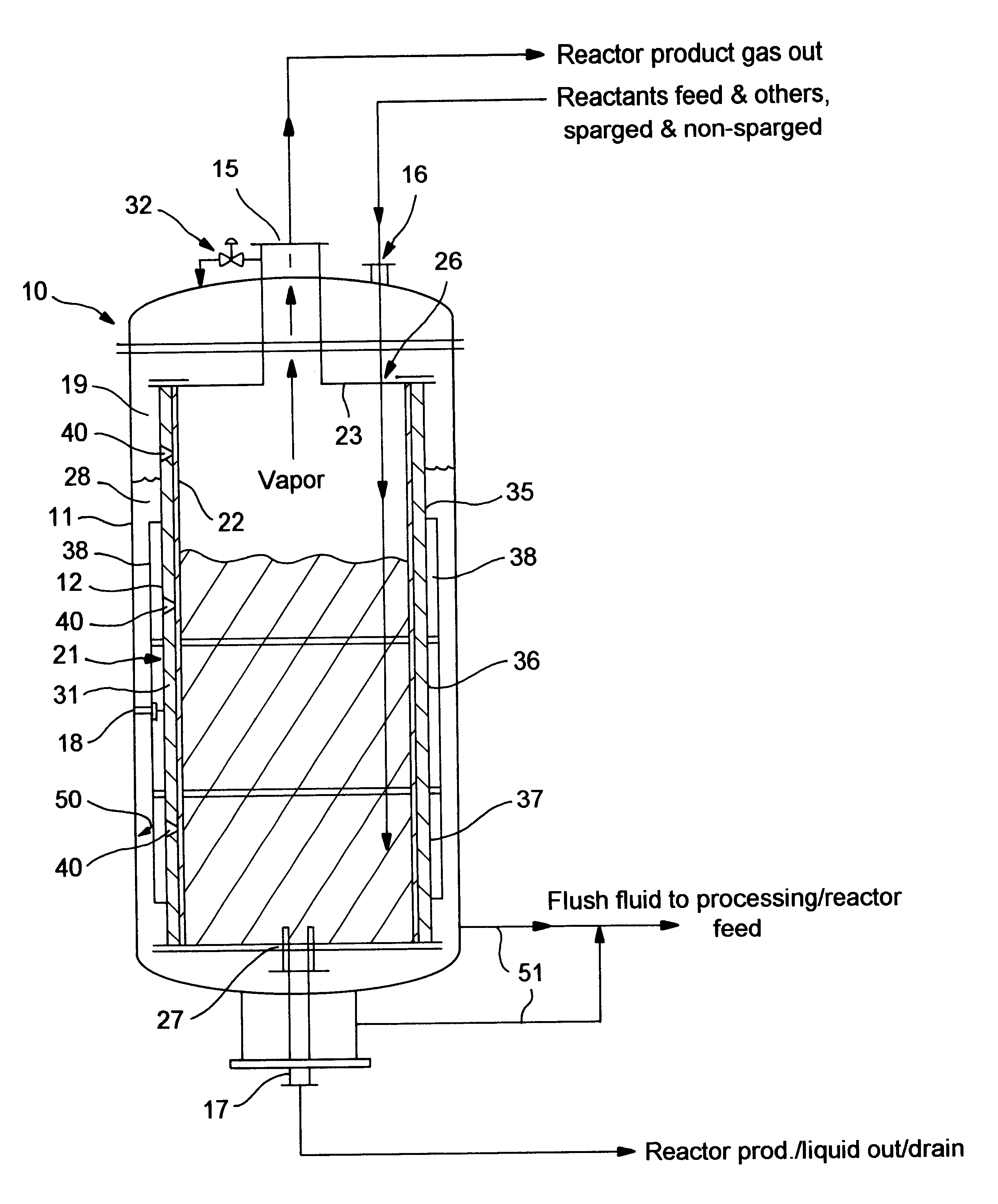
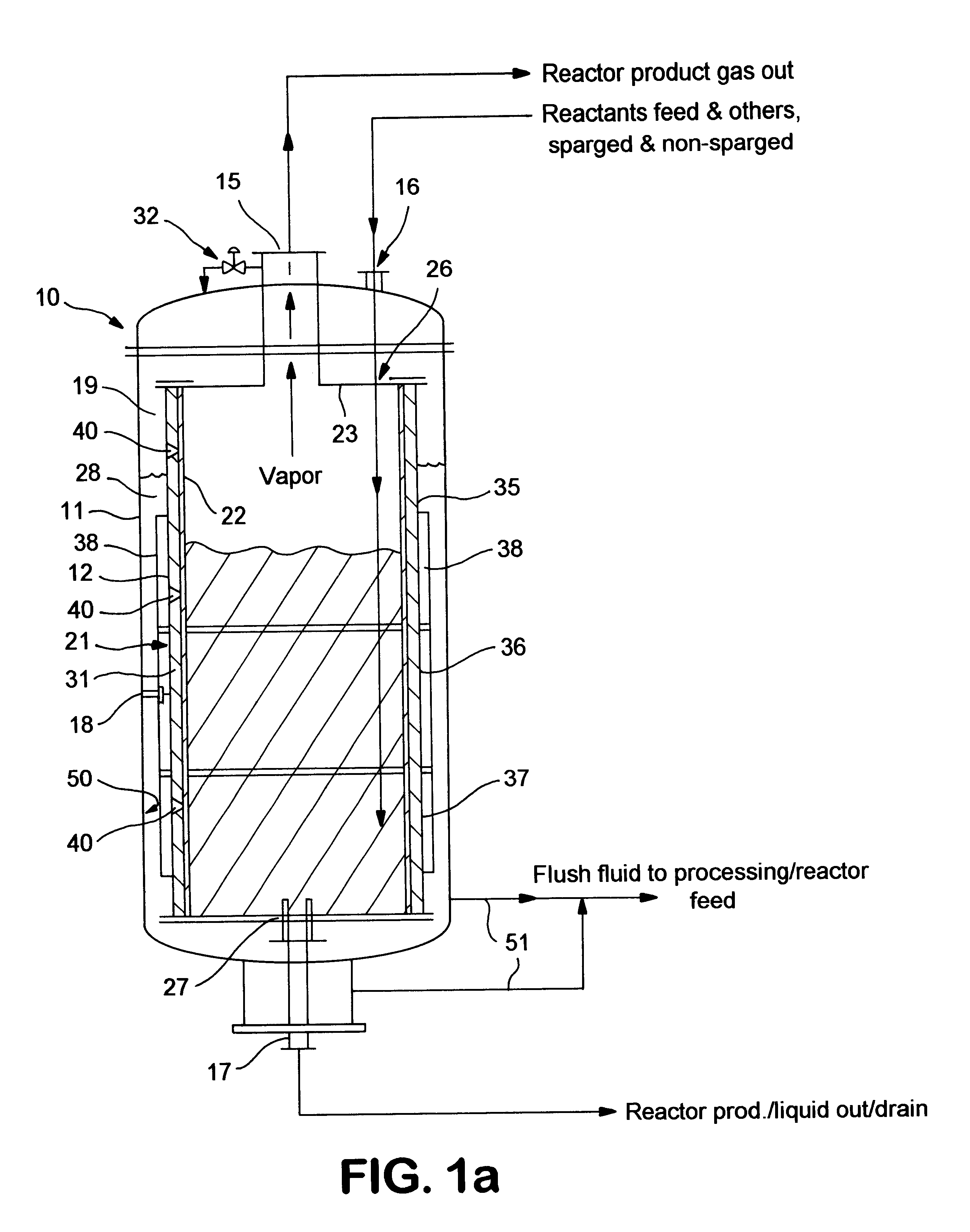
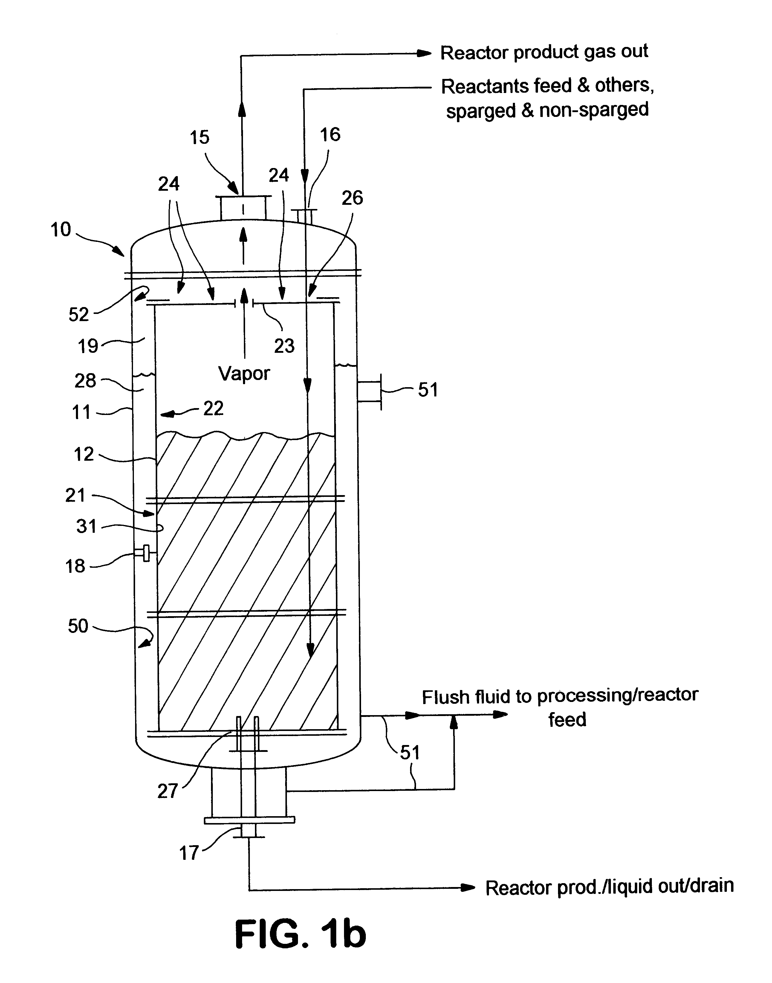
[0009]The reactor apparatus of the present invention facilitates heat transfer several ways. First, the annular space is adapted to contain one or more fluids, either liquid or gas, which may be externally heated or cooled and circulated within the space. The annular space may also be baffled to impart velocity to the fluid to further enhance heat transfer.
[0010]In addition to accommodating a heat-transfer fluid, the annular space also allows for a thinner reactor vessel wall which tends to improve heat transfer. More specifically, since the outer vessel is constructed to be the pressure-bearing component of the reactor system, the annular space can be pressured to approximately the reaction pressure. This results in near-pressure equalization on either side of the reactor vessel wall. Consequently, the reactor vessel wall does not encounter forces from high pressure differentials and can be constructed with relatively thin walls or it can be constructed totally of a fluoropolymer despite the fluoropolymer's marginal strength.
[0011]The annular space not only provides means of conveniently heating or cooling the reaction, but also improves the reactor vessel's useful life. In a preferred embodiment, the reactor comprises a rigid member and a loose, fluoropolymer liner. The rigid member has weep holes to allow those reactants that permeate the fluoropolymer-lined reactor to vent. This prevents reactants from building up between the liner and the reactor wall and forming blisters or otherwise leading to liner failure. Such a configuration therefore improves the reactor vessel's durability and extends its useful life.
[0012]The annular space accommodates a fluid which flushes away reaction materials escaping from the reactor vessel, and, when pressurized to approximate reaction pressure, the fluid relieves the stress on the fluoropolymer liner spanning the weep hole. Additionally, the fluid in the annular space is easily monitored to detect the existence of a leak. In a preferred embodiment, the fluid used to both impart heat and capture escaping reactants is a starting material which is fed into the reactor after circulating about the annular space. This way, the errant reactants are returned the reactor.
[0013]Therefore, in accordance with the present invention, a commercial-scale reactor may be designed more for corrosion resistance than for strength because the pressure-bearing outer vessel relaxes the structural demands on the reactor vessel. The present invention is especially useful for the liquid-phase fluorination of chlorinated hydrocarbons in which the reaction is very corrosive to conventional metal reactors. However, the system also may be useful for other processes, which may not be particularly corrosive, but would benefit from improved heat transfer and / or leak detection.

Problems solved by technology

The corrosion is acute especially where Lewis-acid catalysts, such as antimony halide catalysts, are used under high reaction pressures and at elevated temperatures.
Under these conditions, strong acids form which tend to corrode reactor vessels, even those comprised of corrosion-resistant materials.
Reactor corrosion compromises the structural integrity of the reactor and reduces its useful life.
Although effective in preventing chemical corrosion, the fluoropolymer component of the reactor tends to be problematic, especially for commercial-scale reactors, for example, over 500 gallons.
Commonly-encountered problems include body flange seal leakage, liner flexing stresses, hydrogen fluoride permeation through the fluoropolymer liner, and blister formation.
Such problems diminish the reactor's durability and lead to premature failure.
Additionally, the fluoropolymer component tends to insulate the reactor thermally, necessitating costly and complex external heat transfer means and procedures.

Method used


Image

  • Fluoropolymer reactor with heat exchange jacket
  • Fluoropolymer reactor with heat exchange jacket
  • Fluoropolymer reactor with heat exchange jacket

Examples


example 1

[0047]This example illustrates the production of 1,1,1,3,3-pentafluoropropane (245fa), which is highly corrosive, in a 2000 gallon reactor vessel, which is generally considered viable for commercial-scale production.

[0048]The reaction apparatus used comprised a 2000 gallon steel reactor vessel lined with a loose, 3 mm thick PTFE sheet, and a 3000 gallon outer vessel which supported and enclosed the reactor vessel. To the reactor vessel were introduced: C3H3Cl5 in the liquid phase, at a temperature of 200° F., at pressure of 160 psig, and at rate of about 4500 lb / hr; and HF at a temperature of 350° F., at pressure of 160 psig, and at rate of 3300 lb / hr. The reactor vessel was pre-charged with 10,000 lb of antimony pentachloride catalyst.

[0049]The product, 245fa (2700 lb / hr), along with HCl (3500 lb / hr) and unreacted starting material (about 1500 lb / hr) were removed in a gaseous product stream and separated using conventional distillation techniques.


PUM

PropertyMeasurementUnit
Thicknessaaaaaaaaaa
Thicknessaaaaaaaaaa
Pressureaaaaaaaaaa

Abstract

A reactor for fluorinating an organic compound comprising (a) an outer vessel; (b) a reactor vessel being disposed within said outer vessel to define an annular space, said reactor vessel at least partially comprising a fluoropolymer, said annular space being adapted to receive a fluid; (c) at least one pathway for introducing said heating fluid into said annular space; (d) at least one pathway for inputing reaction materials into said reactor vessel; and (e) at least one pathway for ouputing a product stream from said reactor vessel.

Description

FIELD OF THE INVENTION[0001]The invention relates generally to a system and method for reacting corrosive materials under pressure. More specifically, the invention relates to a reactor system and method for the liquid-phase fluorination of organic compounds.BACKGROUND OF THE INVENTION[0002]Liquid-phase fluorination involves a mixture of corrosive reaction materials. The corrosion is acute especially where Lewis-acid catalysts, such as antimony halide catalysts, are used under high reaction pressures and at elevated temperatures. Under these conditions, strong acids form which tend to corrode reactor vessels, even those comprised of corrosion-resistant materials. Reactor corrosion compromises the structural integrity of the reactor and reduces its useful life. Therefore, a need exists to minimize reactor corrosion.[0003]A recent approach to combat reactor corrosion involves lining or coating the inside of the reaction vessel with a fluoropolymer. Although effective in preventing che...

Claims


Application Information

Patent Timeline
IPC IPC(8): B01J3/04B01J19/00B01J19/02C07B39/00C07C17/00C07C17/20
CPCB01J3/046B01J19/0013B01J19/02C07B39/00C07C17/206C07C19/08B01J2219/00065B01J2219/00094B01J2219/00162B01J2219/0263Y02P20/582
Inventor CHIU, YUONHAGUE, WILLIAM JAMES
Owner ALLIEDSIGNAL INC
Learn More