
Image processing apparatus and method of same

Inactive Publication Date: 2005-09-06
SONY CORP
View PDF3 Cites 24 Cited by
  • Summary
  • Abstract
  • Description
  • Claims
  • Application Information

AI Technical Summary

Benefits of technology

[0024]An object of the present invention is to provide an image processing apparatus able to efficiently utilize a large number of operation processing elements, having a high degree of freedom in algorithms, having a high flexibility, and able to realize image processing and graphics processing without inducing an increase of the circuit scale and an increase of costs and a method of the same.

Problems solved by technology

In the case of parallel processing by the area division, however, in order to make processing units efficiently operate in parallel, it is necessary to classify the object to be drawn in each area in advance, so the load of the scene data analysis is heavy.
Further, when generating graphics in the so-called immediate mode of not starting to generate graphics after one frame's worth of the scene data is all completed, but starting to generate the graphics immediately after the object data is given, the parallel property cannot be derived.
When this difference becomes large, the areas for drawing by the processing units become very different and the locality of the data is lost, therefore a “page miss” of for example the DRAM configuring the memory module frequently occurs and the performance falls.
Further, in the case of this technique, there is also the problem of a high interconnect cost.
Simple combination of two processors, however, gives rise to the disadvantages of for example the circuit scale increasing and an increase of the cost being induced.
In parallel processing at the command level, however, there is a limit in parallelism, so this is not suited for efficient utilization of a large number of operation processing elements.
This approach gives a high ratio of performance to area since the connections among operation processing elements are fixed and the interconnect overhead is small, but has the disadvantages that there is no freedom in the algorithms and the flexibility is low.

Method used


Image

  • Image processing apparatus and method of same
  • Image processing apparatus and method of same
  • Image processing apparatus and method of same

Examples


Embodiment Construction

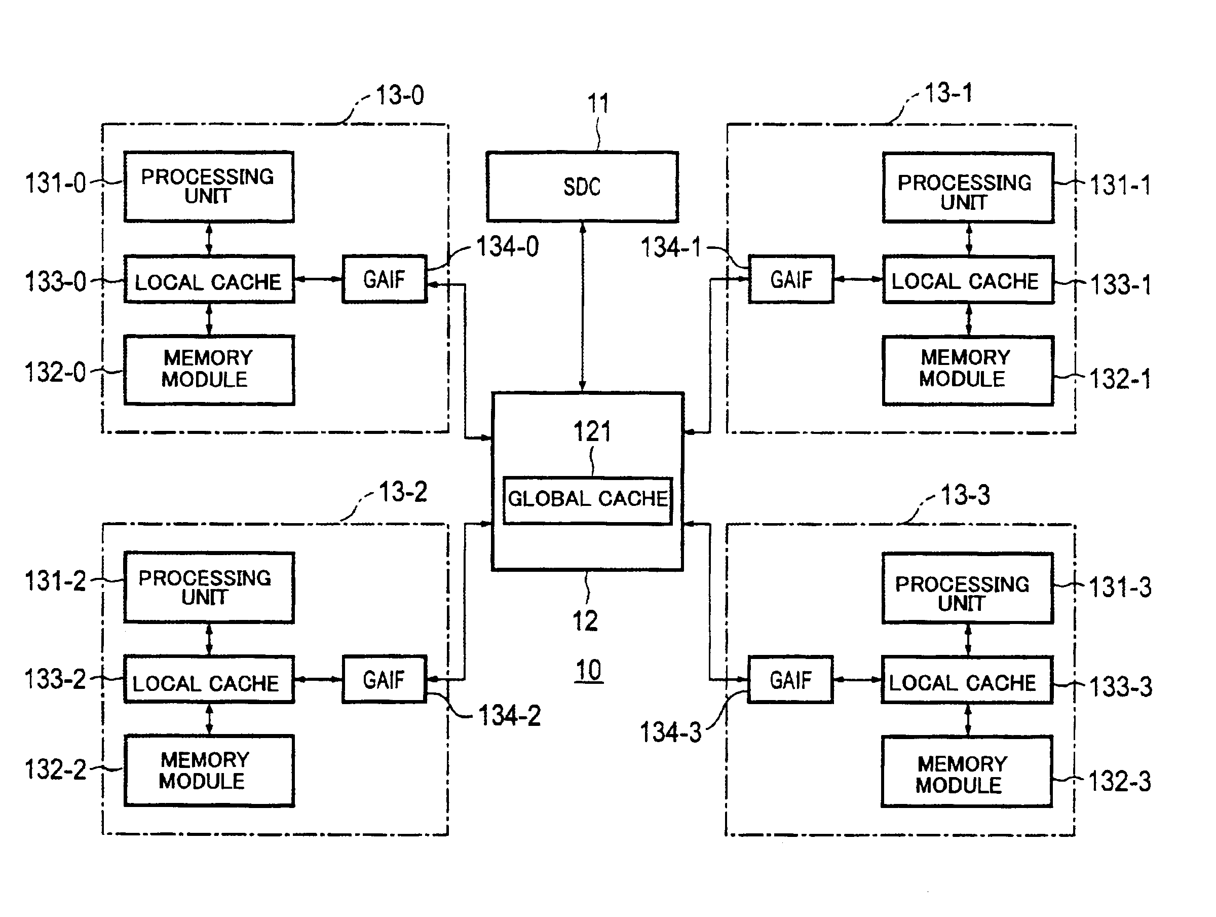
[0107]FIG. 3 is a block diagram of the configuration of an embodiment of an image processing apparatus according to the present invention. An image processing apparatus 10 according to the present embodiment has, as shown in FIG. 3, a stream data controller (SDC) 11, a global module 12, and a plurality of local modules 13-0 to 13-3.

[0108]The present image processing apparatus 10 transfers data between the stream data controller (SDC) 11 and the global module 12. In the present embodiment, local modules 13-0 to 13-n are connected in parallel to one global module 12. A plurality of local modules 13-0 to 13-3 share processing data and process them in parallel. For the texture read system, memory access to other local modules is necessary, but instead of the format of a global access bus, access is performed via one global module 12 having a function as a router. The global module 12 has a global cache, while each of the local modules 13-0 to 13-3 has a local cache. Namely, as the level...


PUM


Abstract

An image processing apparatus able to efficiently utilize a large amount of operation processing elements, having a high degree of freedom of algorithms, and having a high flexibility, provided with a rasterizer for generating pixel data or addresses; a graphics unit for generating graphics data based on texture coordinates; a pixel operation processor for performing operations based on the graphics data and performing image processing with respect to the image data in accordance with source addresses at the time of image processing; a pixel engine for performing operations with respect to the operation data of the pixel operation processor set in a register based on the color data; and a write unit for performing processing required for pixel writing based on window coordinates and the operation data of the pixel engine set in the register at the time of graphics processing and writing the processing results into a memory according to need and writing the operation data of the pixel operation processor set in the register at a destination address of the memory at the time of image processing, and a method of the same.

Description

BACKGROUND OF THE INVENTION[0001]1. Field of the Invention[0002]The present invention relates to an image processing apparatus having a graphic processing function and an image processing function and sharing a plurality of strings of processing data for parallel processing and a method of the same.[0003]2. Description of the Related Art[0004]Along with the improvement of operating speeds and strengthening of drawing functions in recent computer systems, computer graphics (CG) technology for preparing and processing graphics and images using computer resources is being actively researched and developed and put into practical use.[0005]For example, in three-dimensional graphics, the optical phenomenon where a three-dimensional object is illuminated by a predetermined light source is expressed by a mathematical model and the surface of the object is given shading or brightness or further given a texture based on this model so as to generate a more realistic, three-dimensional-like two...

Claims


Application Information

Patent Timeline
IPC IPC(8): G06T1/20G06F15/16G06F15/80G06F17/10G06T15/00
CPCG06T1/20
Inventor YAMAGUCHI, YUJISATOH, JINIGARASHI, MASAHIRO
Owner SONY CORP
Learn More