
Method and facility for producing silane

Inactive Publication Date: 2005-09-13
EVONIK DEGUSSA GMBH
View PDF13 Cites 26 Cited by
  • Summary
  • Abstract
  • Description
  • Claims
  • Application Information

AI Technical Summary

Benefits of technology

[0013]The object of the invention is to indicate a continuous process as well as a facility for producing silane by catalytically disproportionating trichlorosilane to silane and silicon tetrachloride, in which process disproportionation takes place by means of reaction / distillation on catalytically active solid matter and silane and silicon tetrachloride are obtained in relatively high concentrations while the effort required for separating the disproportionated products and condensing them is reduced to a minimum. Heat is to be substantially carried away at a temperature level at which coolants having a temperature that can be achieved without great effort can be used in order to reduce the equipment and energy effort required to produce cold which is needed to carry away heat in order to condense the products.

Problems solved by technology

Liquid catalysts, as selected in some of the processes described, are disadvantageous in that they are gradually dragged out of the reactor since they can in no case be separated completely from the reaction products.
The amounts of catalyst dragged along cause problems in subsequent process steps, or also in upstream process steps in case of a circulation system, since they can collect at certain places of the system and e.g. catalyse undesired reactions there.
In addition, a liquid catalyst cannot be successfully distributed in the column as evenly as possible, but it will concentrate locally due to its specific steam pressure.
However, a serious disadvantage of the aforesaid process described in DE OS-2 507 864 consists in that the amount of energy used for separating the silanes or chlorosilanes has to be carried away completely at a very low temperature level corresponding to the condensation temperatures.
As is generally known, carrying away heat at low temperature levels is costly and causes additional energy consumption, with costs and energy required increasing the lower the temperature of the cooling medium has to be set.

Method used


Image

  • Method and facility for producing silane
  • Method and facility for producing silane
  • Method and facility for producing silane

Examples


second embodiment

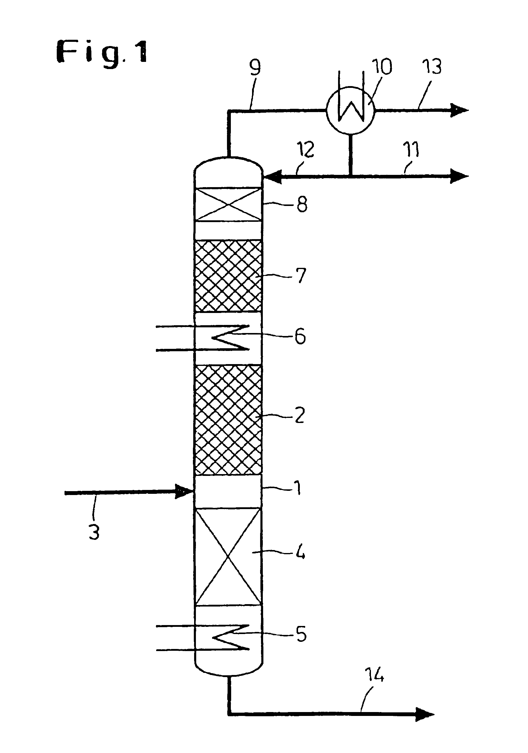
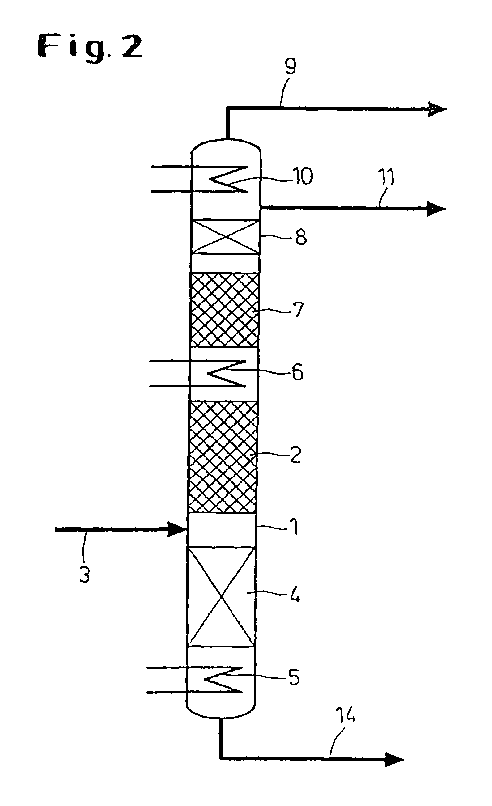
[0039]FIG. 2 shows the invention. The configuration of the reaction column 1 is substantially the same as in the embodiment according to FIG. 1. All parts of the apparatus which are designed analogous to the parts according to FIG. 1 are designated by the same reference numerals. In contrast to the embodiment described above, the top condenser 10 in the embodiment according to FIG. 2 is not arranged externally outside the column, but integrated into the reaction column 1. The integration of the top condenser 10 into the reaction column 1 enables space to be saved, on the one hand, and provides advantages with respect to industrial safety, on the other, since the holdup containing silane inside the facility is reduced.

third embodiment

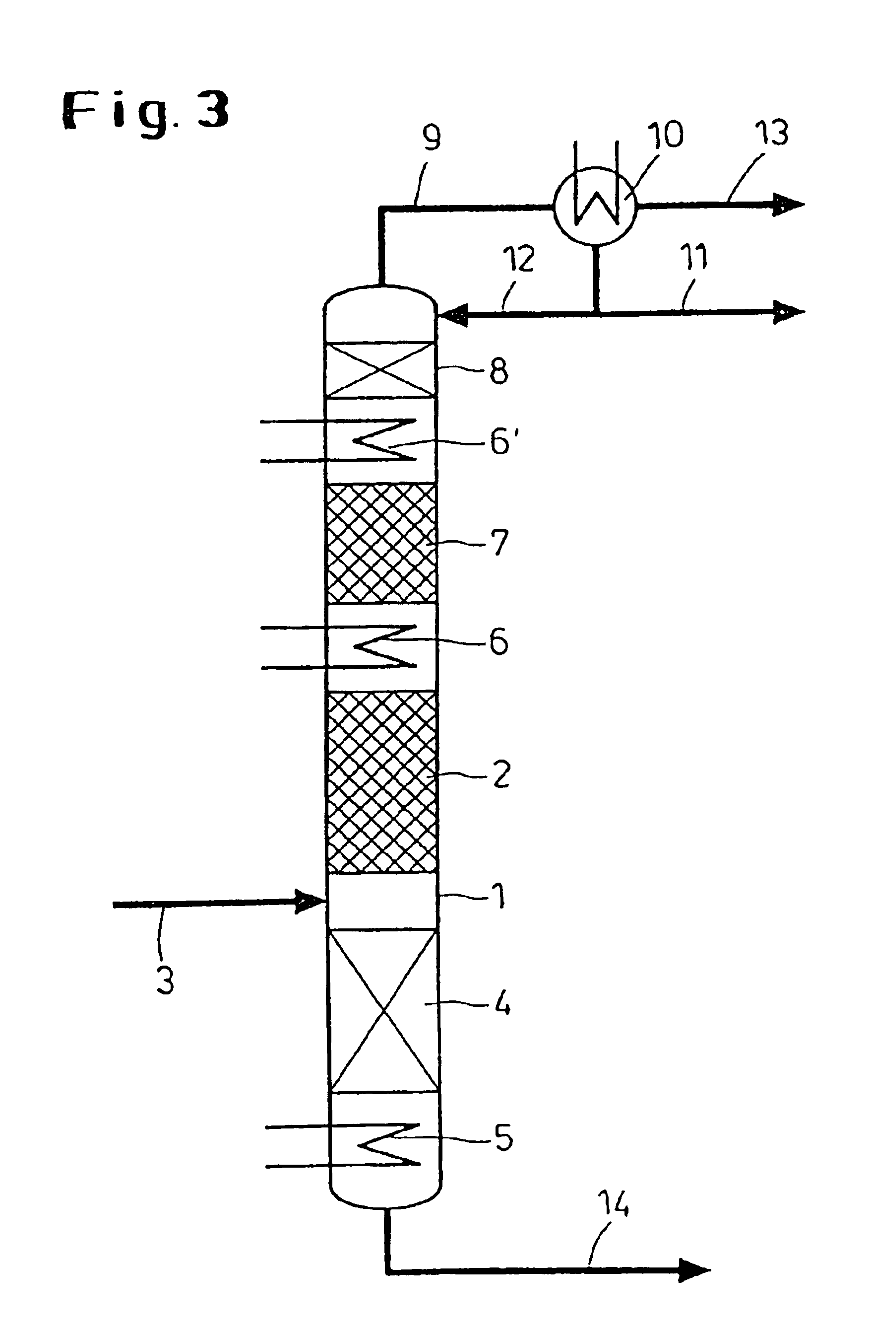
[0040]In FIG. 3, a third embodiment is shown by way of example. This embodiment also substantially corresponds to the embodiment according to FIG. 1. All parts of the apparatus which are designed analogous to the parts according to FIG. 1 are designated by the same reference numerals. In the embodiment according to FIG. 3, the reaction column 1 is equipped with two intercondensers 6 and 6′ instead of a single one. The use of two or more intercondensers enables the heat of intercondensation to be carried away in an exergetically advantageous manner at different temperature levels while the driving temperature differences are small.

[0041]Advantageously, 1 to 5 intercondensers, preferably 1 to 3, particularly preferred 1 to 2, are used according to the invention.

[0042]A fourth exemplary embodiment according to the invention is illustrated in FIG. 4. This example shows the use of a separating column 15 which is arranged downstream of the reaction column 1 of the exemplary embodiment 1 a...


PUM


Abstract

Silane is produced in a continuous process by disproportionating trichlorsilane in at least 2 recreation areas for reaction / distillation, which are run through by a countercurrent of steam and liquid in the presence of catalytically active solid under a pressure which ranges between 500 mbar and 50 bar.

Description

FIELD OF THE INVENTION[0001]The present invention refers to a continuous process for producing silane SiH4 by catalytically disproportionating trichlorosilane SiHCl3 to SiH4 and silicon tetrachloride SiCl4. The invention also refers to a facility for carrying out the aforesaid process.BACKGROUND OF THE INVENTION[0002]SiH4 is an excellently suitable starting material which, following further purification if necessary, can be pyrolysed in order to separate very pure, semiconductor-quality silicon. The demand for high-purity silicon is growing strongly and so does the demand for pure silane whose excellent suitability for the production of high-purity silicon is increasingly recognized and utilized.[0003]Among the processes for producing silane described in the literature, the production from trichlorosilane by means of disproportionation is advantageous from an economic point of view. It is known that amines, in particular tertiary amines and their hydrochlorides and quaternary ammoni...

Claims


Application Information

Patent Timeline
IPC IPC(8): B01J8/04C01B33/04C01B33/00B01J8/02C01B33/107
CPCB01J8/0453B01J8/0496C01B33/043B01J2208/00203B01J2208/00256B01J2208/00274B01J2219/00006
Inventor MULLER, DIRKRONGE, GEORGSCHAFER, JOHANNES-PETERLEIMKUHLER, HANS-JOACHIMSTRAUSS, ULRIKEBLOCK, HANS-DIETER
Owner EVONIK DEGUSSA GMBH
Learn More